E.R.I.C. Hind Leg Implementation Pt 1
In the previous pages I have explained how to find the leg's joint angles from a given toe position and then worked back to show that given a set of angles the toe position can be derived. This abstraction has several challenges to cope with when implementing the maths in E.R.I.C.s legs.
Servo Configuration
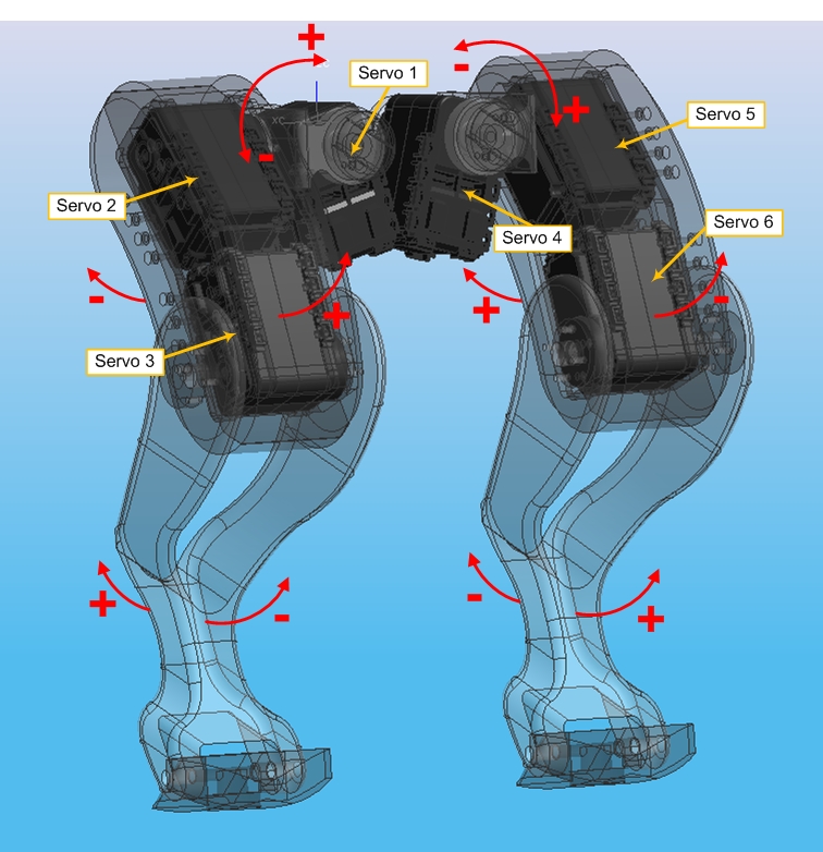
The hind legs consist of six servos - three for each leg. The two legs are mirrors of each other. The figure below shows the servo ID and their articulation.

This diagram shows that, (for example) E.R.I.C.'s left leg is comprised of servos four, five and six, and that Servo six controls the tibia which extends the leg if the servo angle is increased. Using this diagram it is possible to see which servos need to be moved in which direction to move the hind legs. Notice that because the legs are mirrors of one another changing the angle of a servo in a certain direction has the opposite effect on the other leg's corresponding servo.
Inverse Kinematics
I have already shown in my Inverse Kinematics page how to work out joint angles for the right hind leg. But how different is the procedure for the left hind leg? Both legs have the same physical dimensions and servo configuration but are mirrors of one another.
So what does this mean? Well if the same global co-ordinate system is used then to 'cock' the left hind leg a negative X-axis value must be used. The Y-axis and Z-axis will be the same but the hip joint angles on the left hind leg must decrease to move the leg forward (increase the toe position in the Y-axis) while on the right leg they must increase.
Lets start by examining the abstraction of the inverse kinematics process for the right hind leg.
- Calculate XZ plane leg length (A)
- Find beta
- Calculate gamma
- Using beta and gamma derive the lateral servo angle (alpha)
- Calculate the 3D leg length (D)
- Derive the knee servo angle (phi)
- Work out epsilon
- Work out delta
- Using epsilon and delta find the hip servo angle (theta)
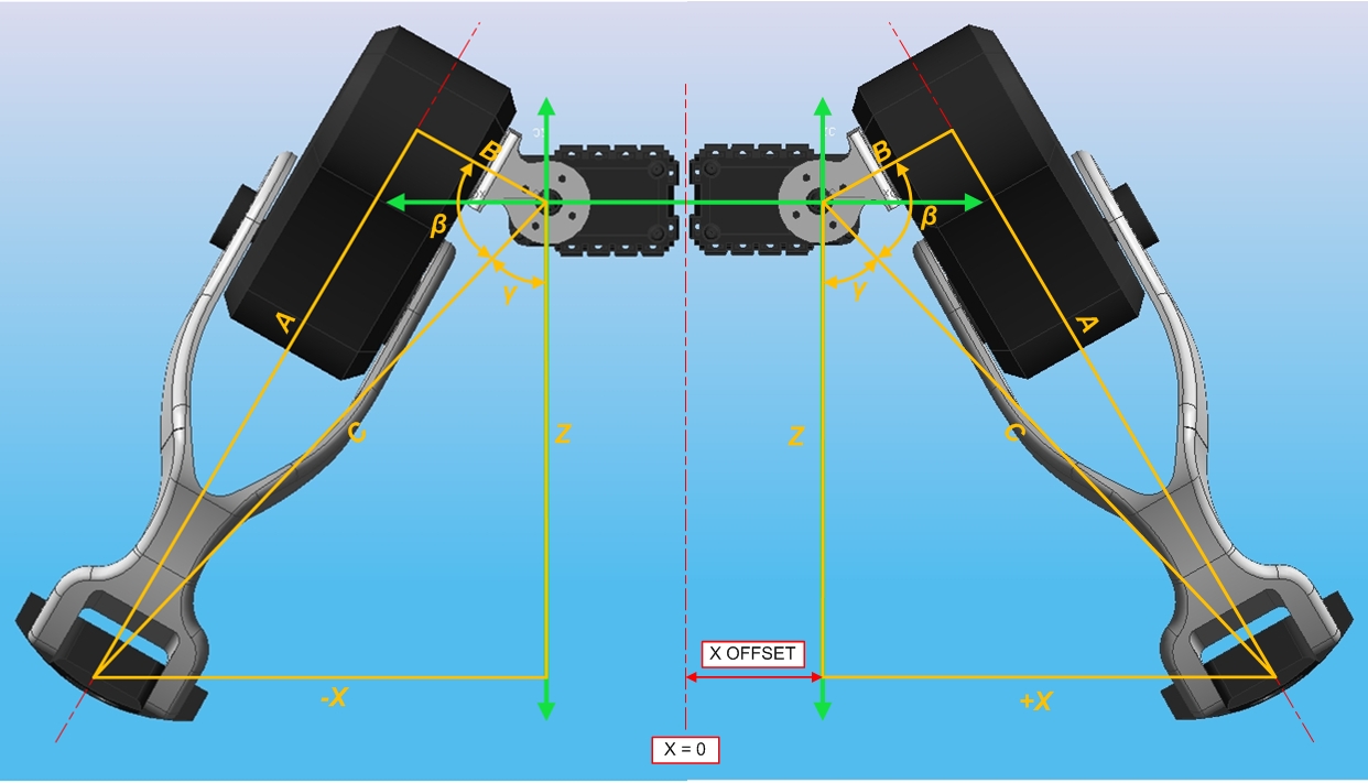
Working through these steps I will discuss the differences in the inverse kinematic equations between the two hind legs. Looking at the figure below it can be seen that the the X offset must be taken into account in all calculations. Bearing this in mind for the leg positions shown here all lengths and angles are the same for both legs The only difference is the X dimension which is positive for the right leg and negative for the left.

This will not effect the equation for calculating C or A as the X dimension is squared during the calculation. β also will not be effected as A and B will always be positive. γ will be effected - it's sign will be reversed for each leg. The knock on effect of this is that the equation for the lateral servo angle will also need amending.
However if I were to change the equation to use Z and C instead of X then this would not be the case.
New Equation 4
γ = arctan X/Z
becomes...
γ = arccos Z/C
Because Z is normally negative Z/C will be negative, meaning the arccos calculation will return an angle that is 180° - γ. This works in my advantage and simplifies the calculation for α to...
New Equation 5
α = γ - β
This holds true for both legs as X is no longer used in the equations. In fact X is not used anywhere else in the inverse kinematics engine.
Side Effect
The down side of this is that I now can't use X values of <0 as they will be interpreted as positive values instead! This is not a problem because the mechanical make up of E.R.I.C. prohibits this anyway! Additionally it would create a very unstable foot position.
With this cleared up I can start wrapping the inverse kinematics code up into a stand alone function.
IK Function
To wrap this up into a nice neat function I first create a header file. A X_OFFSET value was added to translate global X co-ordinates into geometry relevant to the individual leg.
IK.h
#include "mbed.h"

#define B 45                // Offset dimension
#define E 80                // Femur length
#define F 140               // Tibia length
#define X_OFFSET 30         // Distance from the X-axis -> servo centre
#define PI 3.14159

/********** Global structures **********/
struct Joint_Angles {
    float lateral;
    float hip;
    float knee;
};

/********** Functions **********/
Joint_Angles IK_Engine(int, int, int);
This header file contains the #define statements and a struct to hold the leg's joint angles
The next file is the Inverse Kinematic Engine (IK_Engine.cpp). This function takes in X, Y and Z co-ordinates and return the required joint angles via the struct above. The code is thus...
IK_Engine.cpp
#include "IK.h"

Joint_Angles IK_Engine(int X, int Y, int Z){

    // Adjust X to account for the X-axis offset
        if(X > 0)
            X = X - X_OFFSET;
        else
            X = X + X_OFFSET;

    // Calculate Leg length
        float A = X*X+Z*Z-B*B;
        A = sqrt(A);

    // Calculate beta
        float beta = A/B;
        beta = atan(beta);
        beta = beta * 180 / PI;

    // Calculate C
        float C = X*X+Z*Z;
        C = sqrt(C);

    // Calculate gamma
        float gamma = (float)Z / C;
        gamma = acos(gamma);
        gamma = gamma * 180 / PI;

    // Calculate alpha (i.e. lateral servo angle)
        float alpha = gamma - beta;

    // Calculate the length of the leg
        float D = A*A+Y*Y;
        D = sqrt(D);

    // Work out phi (i.e. knee servo angle)
        float phi = E*E+F*F-D*D;
        phi = phi / (2*E*F);
        phi = acos(phi);
        phi = phi * 180 / PI;

    // Work out epsilon
        float epsilon = E*E-F*F+D*D;
        epsilon = epsilon / (2*D*E);
        epsilon = acos(epsilon);
        epsilon = epsilon * 180 / PI;

    // Work out delta
        float delta = (float) Y/ A;
        delta = atan(delta);
        delta = delta * 180 / PI;

    // Work out theta (i.e. hip servo angle)
        float theta = 180 - delta - epsilon;

    // Return calculated joint angles
        Joint_Angles angles;    // Local variable
        angles.lateral = alpha;
        angles.hip = theta;
        angles.knee = phi;
        return(angles);
 }
Finally, the main function now just calls the IK_Engine function and sends it the desired set point. The results are then printed to a terminal. The main code is below.
main.cpp
#include "IK.h"

int main() {
    Serial pc(USBTX,USBRX);

    int LHS_X = 155;
    int RHS_X = -155;
    int Y = 50;
    int Z = -150;

    Joint_Angles LHS = IK_Engine(LHS_X,Y,Z);
    Joint_Angles RHS = IK_Engine(RHS_X,Y,Z);

    // Print output for LHS to terminal
        pc.printf("\n\r LHS Lateral Joint = %.3f",LHS.lateral);
        pc.printf("\n\r LHS Hip Joint = %.3f",LHS.hip);
        pc.printf("\n\r LHS Knee Joint = %.3f\n",LHS.knee);

    // Print output for RHS to terminal
        pc.printf("\n\r RHS Lateral Joint = %.3f",RHS.lateral);
        pc.printf("\n\r RHS Hip Joint = %.3f",RHS.hip);
        pc.printf("\n\r RHS Knee Joint = %.3f",RHS.knee);
}
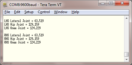
When run the terminal output is as shown below.

This shows that the joint angles are the same for both legs, despite the fact that the X-axis values for the two legs are 155 mm and -155 mm from the centre of the body respectably.
Further Work
I think that this page is long enough already! But I next want to go over the Forward Kinematics for the other leg and investigate if that can be wrapped up into a function also.
I will probably add some debugging statements in the code shown here for future testing.
Finally I need to investigate a translation function that converts the joint angles found here into target servo angles for the AX-12+ servos. This will involve finding where the 0° point is for the servos as they lie in the legs and articulating them to mimic walking. The next part to this page can be found here
Please log in to post comments.
