E.R.I.C. Leg Inverse Kinematics
A walk-through of the maths behind E.R.I.C.s leg motion
As the design of the leg permits only 3 D.O.F. it is possible to solve mathematically the joint angles for any physically achievable foot position. The process to complete this is as follows:
- Ascertain the lateral hip joint angle
- Calculate the required length of the leg
- Calculate the knee joint angle
- Derive the hip joint angle (requires two stages of calculation)
Ascertain the lateral hip joint angle
Laterally the leg only has 1 D.O.F. and thus the foot position in the X plane will be solely dependant on the hip joint lateral angle (α), the lateral offset of the shoulder joint and the leg length (A). These variables are depicted graphically in the figure below that shows the view from behind E.R.I.C.
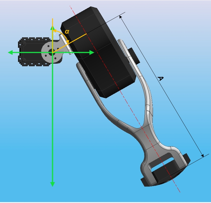
Ultimately the aim is to find α along with the angles of the remaining two leg servos. To do this several other dimensions need to be constructed and calculated.
Firstly an additional line (B) can be drawn in to represent the lateral offset of the shoulder joint. This is a mechanical constant which is 45 mm. Next a second line(C) can be constructed by joining the leg origin (point 0,0) with the point that the toe intersects the leg centreline. This allows the triangle ABC to be created and the angle β to be defined. In addition to this a second triangle can be created by using the desired toe position in the X and Z planes (triangle CXZ). This allows the angle γ to be defined.
A figure depicting these constructs and dimensions is shown below.
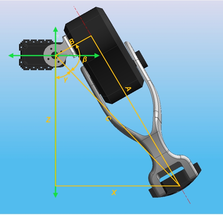
The length of the hypotenuse of the triangles, C can be calculated using Pythagoras's theorem, i.e.
Equation 1
C = √ X² + Z²
Now that C is known A can also be calculated using Pythagoras's theorem.
Equation 2
A = √ C² - B²
Combining the two equations by expressing C in terms of X and Z means the equation for calculating A can be simplifed to:
Equation 3
A = √ X² + Z² - B²
Once the lengths A and B are known, the angles α and β can be calculated in a number of different ways using trigonometry. In this case the following equations were be used.
Equation 4
β = arctan A/B and γ = arctan X/Z
Because when the toe is below the hip joint Z will be negative, γ will also be negative (this is not true if the toe is raised above the hip of course!). This means that the hip joint lateral angle (α) can now be calculated.
Equation 5
α = 180° - β + γ
Calculate the required length of the leg
The 2D length of the leg (A) when viewed from the XZ plane has already been calculated above. To calculate the length of the leg in 3D space the amount of forward displacement (displacement in the Y-axis) must also be considered.
The figure below shows a view in the YZ plane rotated by α. This will always be perpendicular to the Femur and Tibia of the leg itself. The angle δ is used later but is best shown on this slide. δ is the angle between the Femur and the YZ plane.
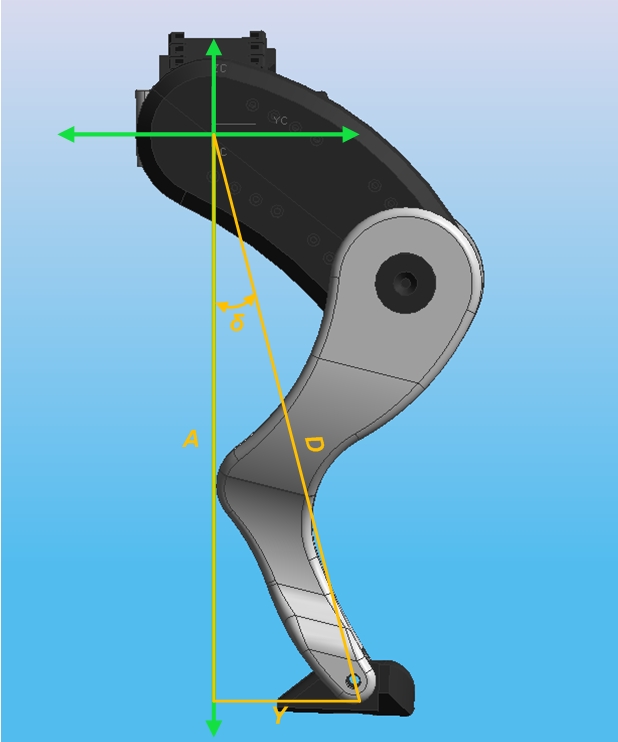
Note how the triangle ADY still intersects with the centre of the foot. The length of the leg in 3D space, D, can be found with the equation
Equation 6
D = √ A² - Y²
Calculate the knee joint angle
To work out the knee angle a new triangle, using the Femur and Tibia (which are both know dimensions on physical components) along with the newly calculated D, is constructed. This triangle (DEF) can be seen in the figure below along with the internal angles ε and φ.
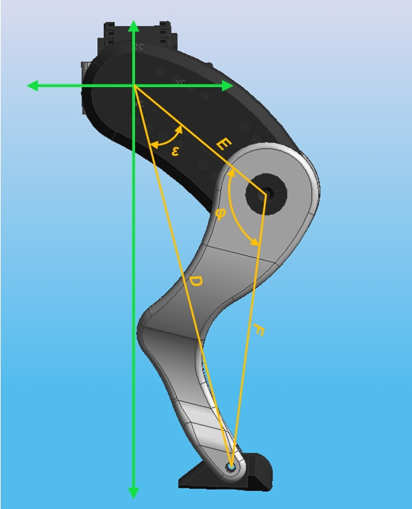
From the above diagram it can be seen that φ is the internal angle between the Femur and Tibia (i.e. the knee angle) while ε is the angle between the Femur and line D.
The law of cosines can be used to calculate φ. This shows the relationship between a triangle and the lengths of its sides. From the triangle shown below:
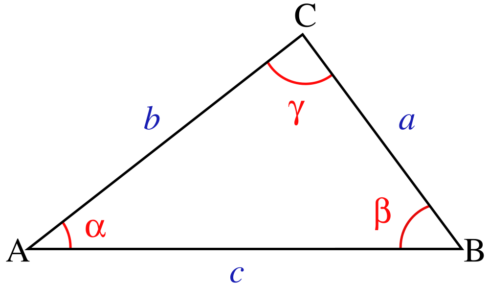
The following formulas can be revealed (from mathworld):
Law of Cosines
cos α = -a² + b²+ c² / 2 b c
cos β = a² - b²+ c² / 2 a c
cos γ = a² + b²- c² / 2 a b
Using these formulae the angle φ can be derived. This is the angle of the knee servo and leaves only the angle of the hip servo to find.
Equation 7
φ = arccos E² + F²- D² / 2 E F
Derive the hip joint angle
This is done in two parts. Firstly the angle ε is calculated, again using the Law of Cosines. Next δ is derived using trigonometry and with these two angles the hip angle is found.
First to calculate ε using the Law of Cosines:
Equation 8
ε = arccos E² - F²+ D² / 2 E D
Next use trigonometry to find the angle δ, which is the angle between the imaginary line between the Femur and Tibia, and the YZ plane. Because of the Y axis value is used in this equation, the result will be a negative number when the Y value is negative.
Equation 9
δ = arctan Y / A
The following diagram shows both δ, ε and the final hip angle (θ) superimposed upon the leg.
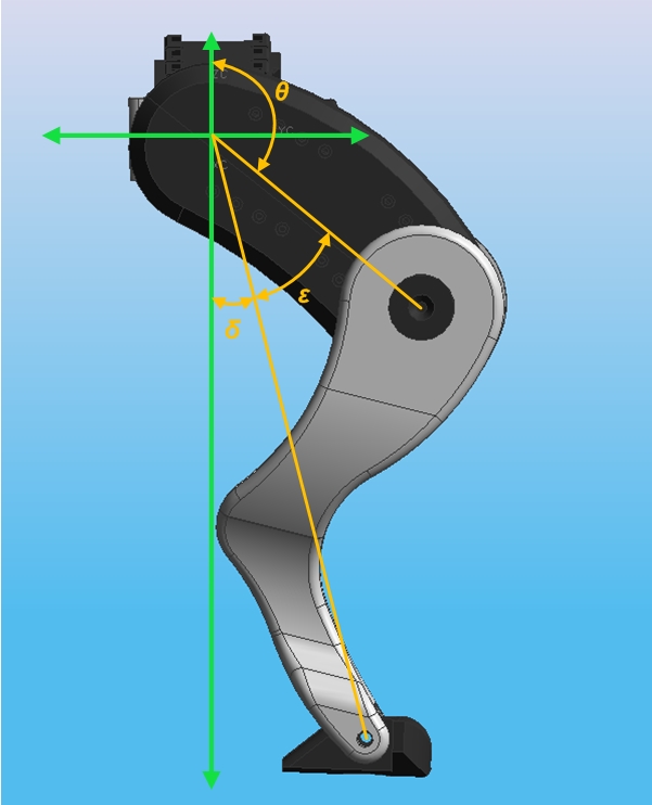
To find the angle θ and complete the inverse kinematics process the following equation is used.
Equation 10
θ = 180° - δ + ε
This concludes the abstraction of the leg inverse kinematics. This document is now converted into code to allow the mbed to find the required angles.
Abstraction into Code
To make the extraction into code I started by defining the set point for the toe and then worked through the equations described above. I mainly worked with floats due to the maths that were required and had to cast the initial X, Y & Z integer variables when using them later on. The code is shown below.
#include "mbed.h"

#define B 45                // Offset dimension
#define E 80                // Femur length
#define F 140               // Tibia length
#define PI 3.14159

Serial pc(USBTX,USBRX);
Timer t;

int main() {
        int X = 125;
        int Y = 50;
        int Z = -150;

       t.start();           // Start the timer

    // Calculate Leg length
        float A = X*X+Z*Z-B*B;
        A = sqrt(A);

    // Calculate beta
        float beta = A/B;
        beta = atan(beta);
        beta = beta * 180 / PI;

    // Calculate gamma
        float gamma = (float) X / (float)Z;
        gamma = atan(gamma);
        gamma = gamma * 180 / PI;

    // Calculate alpha (i.e. lateral servo angle)
        float alpha = 180 - beta + gamma;

    // Calculate the length of the leg
        float D = A*A+Y*Y;
        D = sqrt(D);

    // Work out phi (i.e. knee servo angle)
        float phi = E*E+F*F-D*D;
        phi = phi / (2*E*F);
        phi = acos(phi);
        phi = phi * 180 / PI;

    // Work out epsilon
        float epsilon = E*E-F*F+D*D;
        epsilon = epsilon / (2*D*E);
        epsilon = acos(epsilon);
        epsilon = epsilon * 180 / PI;

    // Work out delta
        float delta = (float) Y/ A;
        delta = atan(delta);
        delta = delta * 180 / PI;

    // Work out theta
        float theta = 180 - delta - epsilon;

    // Measure how long the code took to run
        t.stop();
        float time = t.read();

    // Print output to terminal
        pc.printf("\n\r Toe set point: X = %d, Y = %d, Z = %d\n",X,Y,Z);
        pc.printf("\n\r Ascertain the lateral hip joint angle");
        pc.printf("\n\r   A = %.3f",A);
        pc.printf("\n\r   beta = %.3f",beta);
        pc.printf("\n\r   gamma = %.3f",gamma);
        pc.printf("\n\r   Lateral servo angle (alpha) = %.3f",alpha);
        pc.printf("\n\n\r Calculate the required length of the leg");
        pc.printf("\n\r   D = %.3f",D);
        pc.printf("\n\n\r Calculate the knee joint angle");
        pc.printf("\n\r   Knee servo angle (phi) = %.3f",phi);
        pc.printf("\n\n\r Derive the hip joint angle");
        pc.printf("\n\r   epsilon = %.3f",epsilon);
        pc.printf("\n\r   delta = %.3f",delta);
        pc.printf("\n\r   Hip servo angle (theta) = %.3f",theta);
        pc.printf("\n\n\r Time taken = %.6f seconds",time);
}
I could have maybe achieved the same effect with less code but I felt that it was worth the extra few lines to make the maths more readable. The program was tested using XYZ co-ordinates to represent the images shown in this document above.
Program Testing
When tested the program displayed the calculated variables to a terminal program (in this instance TeraTerm). A screen grab is shown below.
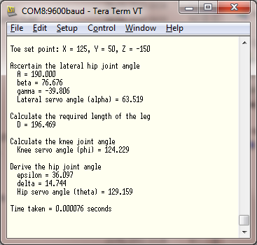
While not verified the values derived here for the three servos seem accurate to the naked eye. The code took 76 microseconds to calculate the angles. So for all four legs it would take around 300 us. With a baud rate communicating with the servos of 1 Mb and a packet length of around 20 bytes it would take about 2.25 ms to calculate and send updated position to all twelve servos on all four legs. So in theory it is possible to update the leg positions at a frequency in excess of 400 Hz!
Further Work
The maths shown here will only work for the right hind leg. The fore limbs have different bone lengths and are articulated differently, while the left hind leg is a mirror copy of the right. This means that portions of the code will need to be configured to find the correct angles for a specific limb.
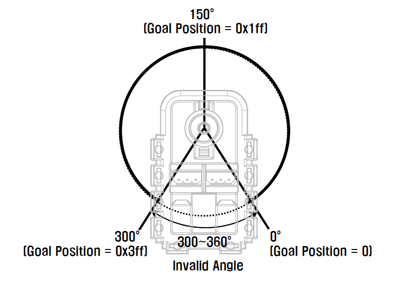
Additionally the 0° position of the AX-12+ servos is not where one might think it is. For instance when the servo is in its mid-point it has a reading of 150°, not the 180° one would expect. This is depicted in the AX-12+ datasheet, a portion of which is reproduced in the image below.
Ultimately I hope to wrap the code shown here up into a function or method and simply call it for a set point and limb.
Please log in to post comments.
