E.R.I.C. Hind Leg Implementation Pt 2
So in my previous notebook page E.R.I.C. Hind Leg Implementation Pt 1 I discussed how inverse kinematics can be used in a real world application. An actual hind leg framework E.R.I.C. will use was defined and resulted in a C++ function that returned joint angles for a given toe position for either hind leg.
This page takes this concept a stage further. Firstly code will be developed to translate the 'joint' angles in 'servo' positions for the six servos that make up the hind legs. Next this process is reversed so that E.R.I.C. can sample the servo positions and using techniques developed in my forward kinematics notebook page work out where its feet are.
Leg Configuration
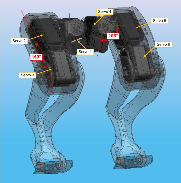
As shown before the hind legs consist of six servos.The important points to note are that the two servos in each femur are not aligned but instead at an inclusive angle of 160°. Additionally the lateral hip servo is kicked over at 105° to allow the two hips to reside closer together while still allowing the leg to move inwards.
These points are shown graphically in the picture below.

Servo Angle Translation
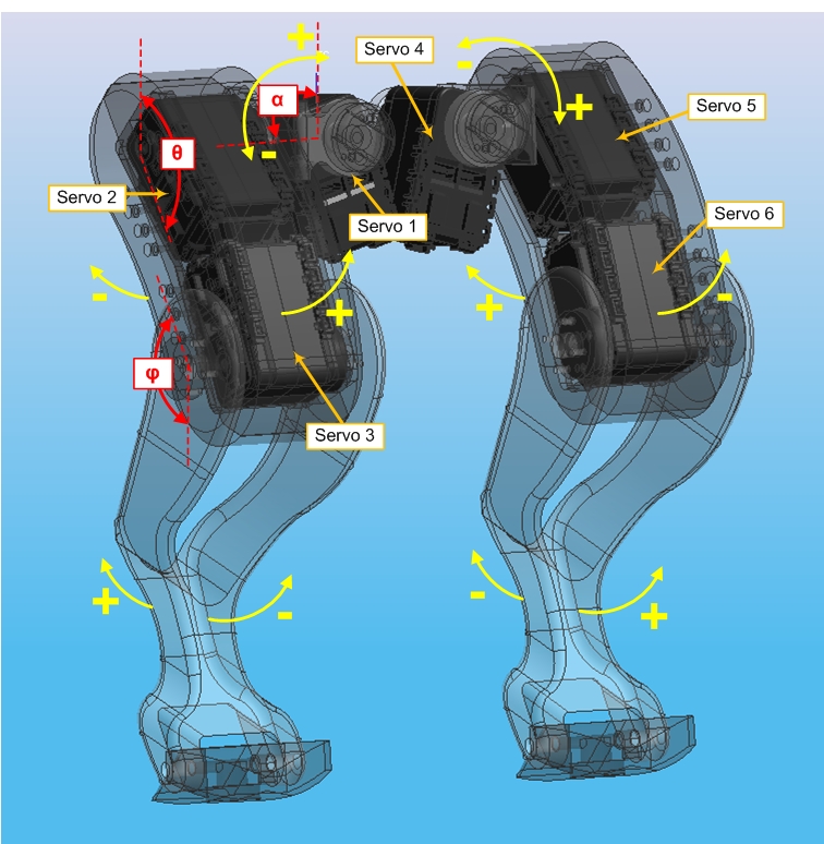
Let's start by showing the angles found so far, i.e. the lateral angle (α), the hip angle (θ), and the knee angle (φ). These are shown in the diagram below.

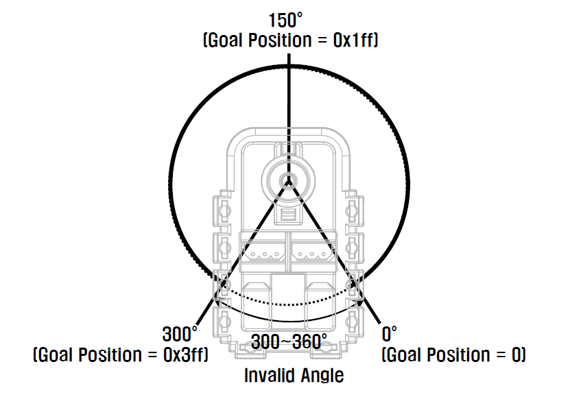
Also useful will be the AX-12+ Servo configuration diagram that shows the angles of the servo.

Looking at this diagram it can be seem that for the lateral servos (servos 1 & 4) when α is 15° the AX-12+ servo will be at 150°. As α increases then Servo 1 will decrease and Servo 4 will increase in angle. This behaviour can be captured in an equation.
Lateral Servo Equations
For Hind Right: Servo 1 = 165° - α
For Hind Left: Servo 4 = α + 135°
The angle for the femur will be 10° less than θ, so when θ is 190° the servos will be 150°. For Servo 2, this angle will decrease as θ increases, while for Servo 5 the opposite is true. Hence the equations will be...
Hip Servo Equations
For Hind Right: Servo 2 = 340° - θ
For Hind Left: Servo 5 = θ - 40°
Finally the angle for the knee servos will be 10° more than φ, so when φ is at 170° the knee servos will be 150°. For Servo 3 this increases as φ decreases. Again the reverse is true for the other leg servo (Servo 6). The equations are:
Knee Servo Equations
For Hind Right: Servo 3 = 320° - φ
For Hind Left: Servo 6 = φ - 20°
Servo Angle Validation
Now that I know the translation between the joint angles and the servo angles, and because I know the maximum and minimum angles that the servos will accept (0° - 300°), I can error check the angles to make sure I'm sending valid data to the servos.
The acceptable range of joint angles derived from the equation above are as follows:
| α | θ | φ | |
| min. | -135 | 40 | 20 |
| max. | 165 | 340 | 320 |
I may have to tinker with this later on to get the leg in some of E.R.I.C.'s poses (for example when sitting the hind leg needs to fold right up on itself), but for the minute I'm happy with this. If a leg position cant be achieved because of the 0° - 300° AX-12+ limitation I can always index the joint round by 90° by attaching it to the next set of holes on the AX-12+.
Forward Kinematics on E.R.I.C.
So now I have a translation between the AX-12+ servo angle readings and the mathematical joint angles α, θ and φ, I can can use the forward kinematics function developed earlier to see where E.R.I.C.'s paws are at any moment in time. The actual translation will be as follows.
AX-12+ Servo to Joint Angle Equations
Hind Right Lateral (α) = 165° - Servo 1 angle
Hind Right Hip (θ) = 340° - Servo 2 angle
Hind Right Knee (φ) = 320° - Servo 3 angle
Hind Left Lateral (α) = Servo 4 angle - 135°
Hind Left Hip (θ) = Servo 5 angle + 40°
Hind Left Knee (φ) = Servo 6 angle + 20°
I now simply need to develop a function to read the servos and report back the toe positions for each leg.
Code Development
To start with I will feed the functions servo angles manually so I don't have to have the leg attached and powered up to develop the code. This will be quite a big function because it will need to calculate the position for both legs.
I'll start with the code I already have and add in a bit at the start to simulate the reading of the AX-12+ servos. Something like this...
Import program3DForwardKinematics
Forward Kinematics code for all four of E.R.I.C.'s legs...
This allows me to validate the maths and after checking I find that the FK engine has arrived at the right result.
Physical Implementation
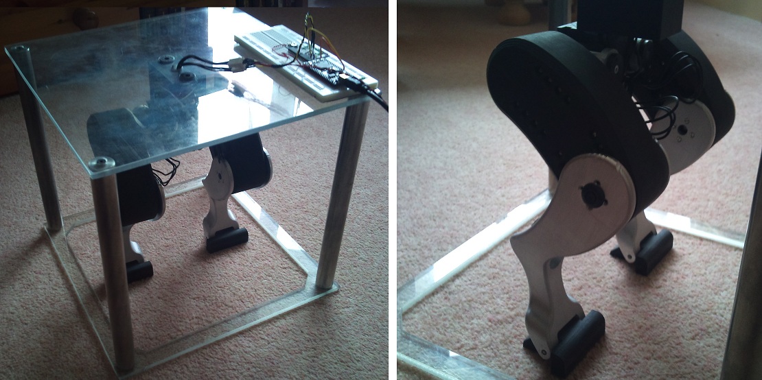
Next I want to get the actual legs working. I have built a rig that contains the legs which is shown in the photo below.

The rig is designed for testing the hind legs and allow them to move freely while being supported within the frame. To test the legs I need to amend the earlier program to create AX-12+ objects for each of the six servos and then read their positions and feed the results into the FK engine. The resulting foot positions can then be displayed on TeraTerm as a set of XYZ co-ordinates for both feet.
The amended code adds in the AX-12+ servos as global objects and reads them instead of simulating them as before. The result when printed to the PC is:

The results seem correct to the leg positions shown in the images above. To test them out further I move each leg in turn in all 3 axis checking that the position indicated moves in the correct manner. So far so good, everything works correctly.
To Do
OK so I'm getting there with the whole leg position thing. I now need to wrap it up and get the legs moving using these function developed here. Then I will be able to set the position of the legs and check that they got there OK. But first I think I need to look at the AX-12 library...
Please log in to post comments.
