Robodog Leg Forward Kinematics
After developing a technique to use the toe set point to derive the required three leg servo angles, I realise that E.R.I.C. will also require the ability to read the three servo angles and calculate its current toe position.
Why Is This Needed?
There are a number of reasons why this would be useful to E.R.I.C's design.
- It gives the ability to check the error between the toe set position and its actual position
- It will allow the limb positions to be found when E.R.I.C. is initially powered up
- It helps with transitions, which can be used by interpolating between current positions and set 'poses' that are stored in memory.
How Does It Work?
There are a variety of different forward kinematics techniques including vectors and trigonometry.
The method I have decided to use is basic trigonometry. The reasons behind this are mainly because due to the limited D.O.F. of the leg (it only has three) it was believed that it would be easier to formulate the maths to solve the problem than developing an algorithm to solve it using vector matrices.
The trigonometry method uses the leg's origin position (co-ordinates 0,0,0) as a starting point and then using the adjoining mechanical component's length and direction finds the co-ordinate position of the next joint. The process is repeated until the end of the limb is reached.
Deriving The Algorithm
Using this method there will be three points that will need to be found.
- The position of the hip joint
- The position of the knee joint
- The position of the toe
Polar notation is the natural starting point, as reading the servos will provide the bearing of the joints, and the length between the joints being known mechanical constants.
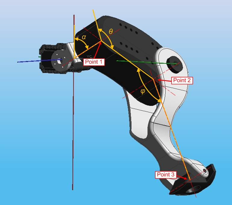
After reading the leg servos the angles of the lateral (α), hip (θ) and knee (φ) servos will be known. This information is depicted in the figure below along with the three points of interest.

Point 1 position
The position of point 1 is soley dependant on α and the lateral offset of the shoulder joint (B) and can be found using trigonometry. The displacement in the X-axis and Z-axis are given by the equations below. The Y-axis is unaffected by this type of motion and will remain at Y = 0.
Equations for point 1
X1 = B * sin α
Y1 = 0
Z1 = B * cos α
Point 2 Position
Point 2 uses point 1 as a starting position and is dependant on the length and angle of the Femur. Position 2 and position 3 lie on a plane that is inclined from the YZ plane by the angle α - 90°.
The X-axis position for point 2 will be dependant on the length of the femur when viewed from the XZ plane (directly behind E.R.I.C.) and the amount that the femur kicks out laterally (determined by α). The XZ length of the femur is given the femur length (a known constant) multiplied by cos (θ + 180°). The amount that the femur kicks out laterally is given by the length from this view multiplied by cos α. The 180° is added to keep the sign correct, the other hind leg (the mirror of this one) will not add the 180° as it's sign will be correct for the same angles.
The Y-axis position for point 2 is just dependant on the angle θ and the femur length and is determined by its sin component.
The Z-axis is the same as the X-axis but uses the cos component of α instead of the sin component.
Using this the position of point 2 can be described in the following terms.
Equations for point 2
X2 = X1 + cos (θ + 180°) * E * cos α
Y2 = Y1 + E * sin θ
Z2 = Z1 + cos θ * E * sin α
Point 3 Position
Point 3 again uses the previous position as a starting position and is effected by the angle of the knee joint. Point 3 will lie on same inclined plane as point 2, so similar equations are used.
The X-axis position is now dependant on the length of the tibia when viewed from behind (XZ plane) and the amount that is laterally protrudes from the body. The XZ length of the tibia is given by the actual tibia length (known constant) multiplied by the cosine of θ minus φ. The amount the tibia protrudes in the X-axis is this XZ length multiplied by cos α (which is the same general equation as for the femur.
The Y-axis position is simply the sin component of the tibia, which is given by the sum of θ and 180° minus φ, multiplied by the length of the tibia.
The Z-axis position takes the same form as for point 2, given by the tibia length in the XZ plane multiplied by sin α.
The equations for point 3 are as follows.
Equations for point 3
X3 = X2 + cos (θ - φ) * F * cos α
Y3 = Y2 + F * sin (θ + 180° - φ)
Z3 = Z2 + cos (θ + 180° - φ) * F * sin α
Deriving the code
The abstract maths found here was coded into an mbed program. It was tested by using the angles found in my other notebook page Inverse Kinematics, if the maths is sound then by putting these angles in the forwards kinematics program should find the toe position specified at the beginning of the inverse kinematics program!
The code is listed below.
#include "mbed.h"

#define B 45                // Offset dimension
#define E 80                // Femur length
#define F 140               // E length
#define PI 3.14159

Serial pc(USBTX,USBRX);
Timer t;

int main() {
    float alpha = 63.519;
    float theta = 129.159;
    float phi = 124.229;
    float temp;     // used to store maths

    pc.printf("\n\r Using Forward Kinematics to calculate toe position");
    pc.printf("\n\r alpha = %.3f, theta = %.3f phi = %.3f",alpha,theta,phi);

    // Start the timer
    t.start();
    // Convert into radians for maths
    alpha = alpha * PI / 180;
    theta = theta  * PI / 180;
    phi = phi * PI / 180;

    // Next calculate point 1
    float x1 = sin(alpha);
    x1 = x1 * B;
    float y1 = 0;
    float z1 = cos(alpha);
    z1 = z1 * B;

    // Now calculate point 2
    float x2 = cos(theta + PI);
    x2 = x2 * E;
    temp = cos(alpha);
    x2 = x2 * temp;
    x2 = x1 + x2;
    float y2 = sin(theta);
    y2 = y2 * E;
    y2 = y2 + y1;
    float z2 = cos(theta);
    z2 = z2 * E;
    temp = sin(alpha);
    z2 = z2 * temp;
    z2 = z1 + z2;

    // Finally calculate point 3
    float x3 = cos(theta - phi);
    x3 = x3 * F;
    temp = cos(alpha);
    x3 = x3 * temp;
    x3 = x2 + x3;
    float y3 = sin(theta + PI - phi);
    y3 = y3 * F;
    y3 = y2 + y3;
    float z3 = cos(theta + PI - phi);
    z3 = z3 * F;
    temp = sin(alpha);
    z3 = z3 * temp;
    z3 = z2 + z3;

    // Measure how long the code took to run
    t.stop();
    float time = t.read();

    // Print the results
    pc.printf("\n\n\r POINT 1: X = %.0f, Y = %.0f Z = %.0f",x1,y1,z1);
    pc.printf("\n\r POINT 2: X = %.0f, Y = %.0f Z = %.0f",x2,y2,z2);
    pc.printf("\n\r POINT 3: X = %.3f, Y = %.3f Z = %.3f",x3,y3,z3);
    pc.printf("\n\n\r Time taken = %.6f seconds",time);
}
Results
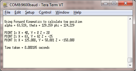
The results were printed to the terminal and can be seen below.

The results show that the maths is correct and the XYZ positions originally used were found. The code took 185 us to run - which is longer than I had hoped. I guess this is down to the large amount of trig functions that are used.
Further Work
This page leads onto the translation between the methods described here into a real world implementation in the form of E.R.I.C.s hind legs.
Please log in to post comments.
