LPC812 MAX Experiment: Getting Started Tour
This section contains a short (and highy recommended) getting started tour to quickly familiarize you with your LPC812 MAX Board.
1. Connect the board to a PC
Connect the HDK USB interface to a PC. A micro-B to A USB cable is needed for this. The HDK USB interface is found on the short side of the board, see picture below.
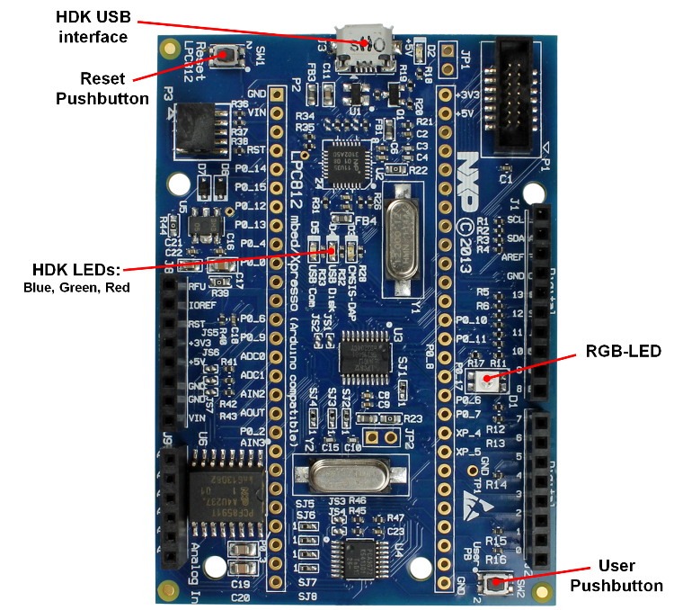
Three LEDs (blue, green, red) will light and after a few seconds of activity, the PC will recognize the LPC812 MAX Board HDK interface as a standard USB drive.
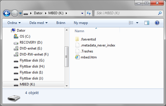
Double-clicking on the mbed.htm file in the new USB drive will take you to the on-line documentation for the board.
2. Register account on mbed.org
You need an mbed account to continue. If you do not have one, signup here and create your account. Otherwise, log in with your normal username and password.
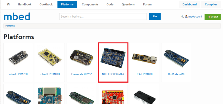
An account gives you access to the on-line compiler. As a first step the LPC812 MAX Board platform should be added to your account. Click on "Platforms" on the toolbar and then select the "NXP LPC800-MAX" platform. The page will likely look different since more platforms are continously added.
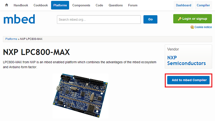
On the page presenting the LPC812 MAX Board, click in "Add to mbed Compiler" button as shown below. The platform is now connected to your account.
It is possible to add more platforms to you account but for now it is best to have just the LPC812 MAX Board connected.
3. Download applications
The next step is to learn how to download a pre-compiled program.
- The on-line compiler creates a *.bin-file as a result of a successful compilation. Save TBD this binary file to the "MBED" USB drive that is created when connecting your LPC812 MAX Board to your PC. The red HDK LED will flash as the file is copied to the board. To be more specific the content of the binary file is programmed into the LPC812 flash memory.
When the binary file has been copied the USB drive will shortly disappear from the PC and then come back on. This is because the HDK restarts the USB disk after any operation. - Press the Reset pushbutton
- The program will start to execute. It is a running pattern on the RGD LED.
Note that the name of the binary file has no meaning. The file is recognized by the bin file ending.
The source code for the pre-compiled program will be investigated in the next step where you learn how to create and compile a program.
The three HDK LEDs have the following meaning:
- Red HDK LED: Flashes when there is activity on the HDK USB drive (when writing a binary file).
- Green HDK LED: Flashes when the CMSIS DAP debug interface is used.
- Blue HDK LED: Flashes when there is serial communication over the virtual USB serial COM channel.
Troubleshooting!
Make sure you save the file to the USB disk that was created when connecting the HDK USB interface to your PC. The name of the drive is be MBED. The drive letter will however be different between different PCs.
- If the red HDK LED did not flash when saving the binary file you probably saved it elsewhere!
- Some browsers default to saving files to your "Desktop", so this should be changed; see Choose-where-to-save-files-FAQ
- Some Linux or old Mac PCs don't write data until you "Eject" the drive; see Mounting-with-sync
Don't try and "Open" or "Run" the program files. Always "Save" them to the "MBED" USB disk.
- Some applications (e.g. VLC Media Player) recognize the .bin extension; ignore them!
Make sure you actually start the program!
- Remember to press the Reset pushbutton to start it after you download a new program
- If the binary file has been copied (i.e., downloaded) but nothing happens after pressing the Reset pushbutton, make sure the correct binary file was copied.
When you unplug the USB cable from the HDK USB interface (i.e., disconnect the board from your PC), you may get a "Device Removal" error message; just ignore it. To avoid the message, you can also use "Eject" (Mac) or "Safely Remove Hardware" (Windows).
4. Create application and compile
The mbed Compiler is an online application used to create your own programs for the LPC812 MAX Board. It translates program source code that you write in to a program binary that the LPC812 microcontroller can execute. A longer introduction to the online compiler can be found here.
The following six simple steps demonstrate how to create an application, compile it and generate the binary file. The download process was covered in the previous step.
4.1. Open the mbed compiler
Open the online compiler using the link in the site menu (top-right of the page). This will open the Compiler in a new browser tab or window.

4.2. Select platform
Make sure the "NXP LPC800-MAX" platform is selected. It should be by default since the "NXP LPC800-MAX" platform was the last one added to your account.

If no platform has been selected the position (upper right corner in the compiler window) will display "No device selected". If this is the case or if some other platform is selected, just press on the position. A new window will pop up where it is possible to change selected platform.
4.3. Create a new program
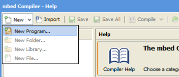
To create a new program in your personal Program Workspace:
- Click in "New" and select "New Program..."
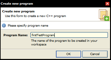
- Enter the name of the new program (e.g. "firstTestProgram"), and click "OK"
- Your new program folder will be created under "My Programs".
4.4. View the default program source code
Click on the "main.cpp" file in your new program to open it in the file editor window. This is the main source code file in your program, and by default it contains a simple LED flashing program already. The code should look like:
main.cpp
#include "mbed.h"

DigitalOut myled(LED1);

int main() {
    while(1) {
        myled = 1;
        wait(0.2);
        myled = 0;
        wait(0.2);
    }
}
4.5. Compile and Download the program
To compile the program, click the Compile button in the toolbar. This will compile all the program source code files within the program folder to create a binary program.
- After a successful compile, you will get a "Success!" message in the compiler output and the download dialog will pop up. Save it to the location of the "MBED" USB disk, and then press the Reset pushbutton on the board to start it!
- The red HDK LED will flash while downloading the binary file.
- If there are errors, they will show up in the "Compiler Output" window, and will need to be fixed!
Troubleshooting!
- Some web browsers and download managers will automatically download files to a predefined location. To configure the download location so you can save it to the "MBED" USB disk, see Choose-where-to-save-files-FAQ
- The compiler only supports some web browsers and platforms; see Which-browsers-are-supported-FAQ
- If you have problems using cut and paste functionality (Ctrl+C, Ctrl+V) in IE7, see Cut-and-paste-IE-FAQ
4.6. Modify program and Recompile
After this simple first program, lets test something more complex and control all four LEDs in a running pattern. Update the code in main.cpp as below. Compile, download and verify the effect.
main.cpp
#include "mbed.h"

DigitalOut myled1(LED1);
DigitalOut myled2(LED2);
DigitalOut myled3(LED3);

int main() {
    //Turn all LEDs off
    myled1 = 1;  //LED1 is active low, turn it off
    myled2 = 1;  //LED2 is active low, turn it off
    myled3 = 1;  //LED3 is active low, turn it off

    //Enter forever loop
    while(1) {
        myled3 = 1;  //Turn LED3 off
        myled1 = 0;  //Turn LED1 on
        wait(0.2);   //Wait 200 ms
        myled1 = 1;  //Turn LED1 off
        myled2 = 0;  //Turn LED2 on
        wait(0.2);   //Wait 200 ms
        myled2 = 1;  //Turn LED2 off
        myled3 = 0;  //Turn LED3 on
        wait(0.2);   //Wait 200 ms
    }
}
Note that all three LEDs are active low meaning that they will turn on when the respective LPC812pin is low.
Experiment with more LED flash patterns!
Try to recreate the flash pattern in the pre-compiled test binary in step 3.
More information about the wait()-function can be found here. There are also wait_ms() and wait_us() functions.
Please log in to post comments.
