Dual CANbus monitor and instrumentation cluster. Presently tuned for the Nissan Leaf EV.
Dependencies: SPI_TFTx2_ILI9341 TFT_fonts TOUCH_TFTx2_ILI9341 mbed
Fork of CANary_corrupt by
After adding the LPC1768 platform, import as a program and do not select the "update to latest revision" box
User Guide
Eagle Schematic and Board design
/media/uploads/TickTock/canaryr6.zip
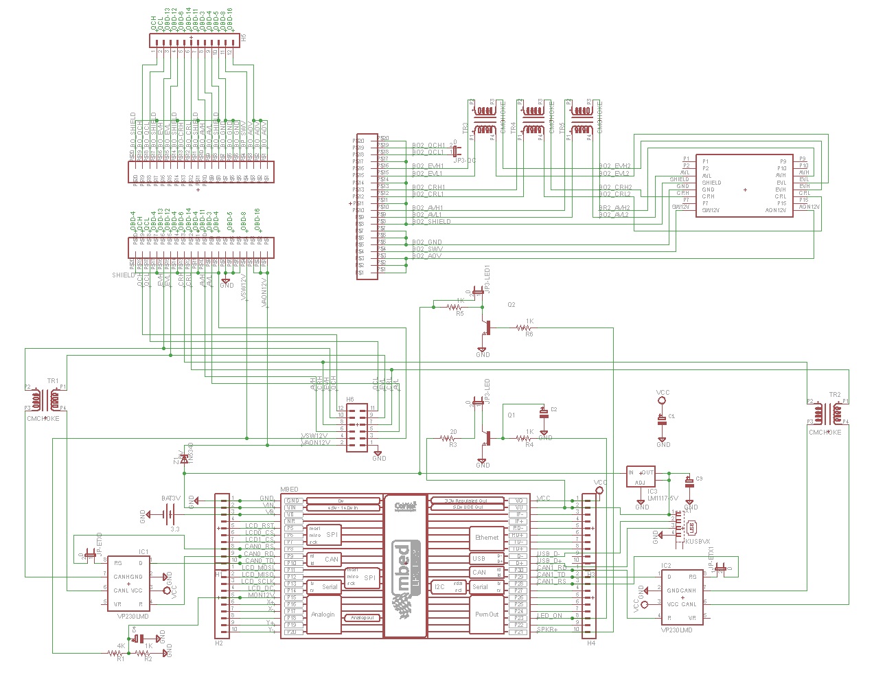
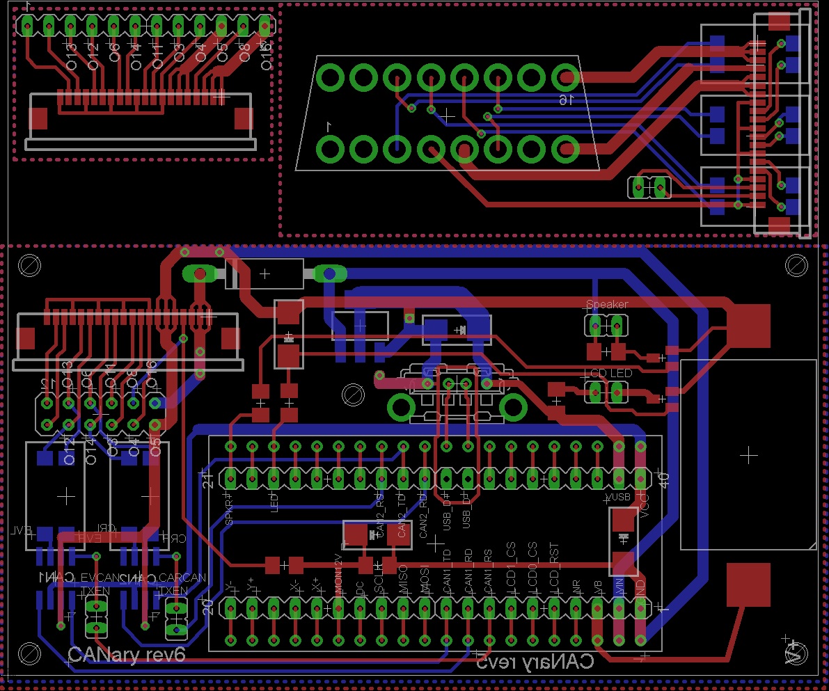
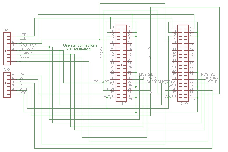
For LCD Rev 1.01:
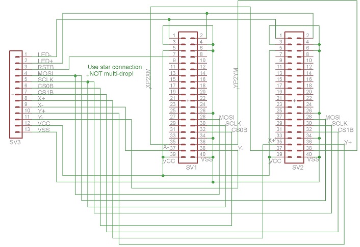
For VCD Rev 2.00:
Parts List
Assembly
1) LCD Displays
I found ribbon cable is a nice way to organize the wires to the displays. There are two versions of the display and each must be wired differently. The original project used HW REV. 1.01. For that version, you'll need 12 conductors and I connected them in the following order:
| 1 | LED+ |
| 2 | LED- |
| 3 | RST |
| 4 | SDI |
| 5 | WR/SCLK |
| 6 | CS |
| 7 | X+ |
| 8 | X- |
| 9 | Y+ |
| 10 | Y- |
| 11 | VDD |
| 12 | GND |
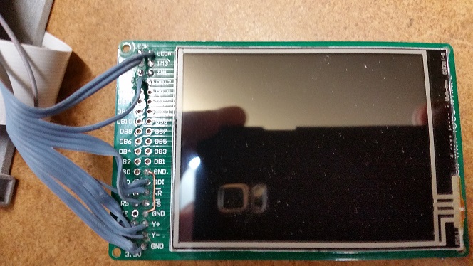
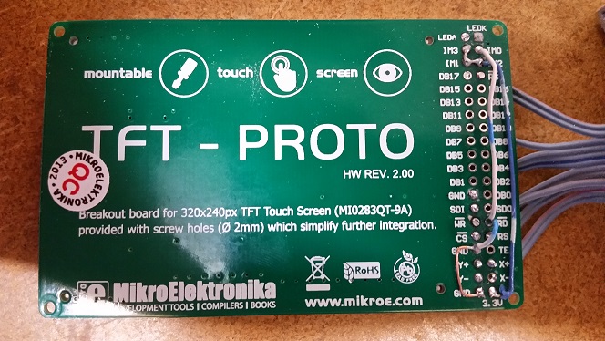
If, instead, you have HW REV 2.0, you will need 13 conductors with the following order:
| 1 | LED+ |
| 2 | LED- |
| 3 | RST |
| 4 | SDI |
| 5 | RS (SCLK) |
| 6 | WR (DC) |
| 7 | CS |
| 8 | X+ |
| 9 | X- |
| 10 | Y+ |
| 11 | Y- |
| 12 | VDD |
| 13 | GND |
First I connected all the GND connections (2 GND & IM0, IM1, IM3 for REV1.01 or 2 GND, RD, & IM0 for REV2.00). Do not connect the bottom GND until you have the ribbon cable connected. After making all the ribbon cable connections (connecting the GND of the ribbon cable to the bottom GND pad), solder the GND bar from the previous step to the back of the bottom GND connection. Finally, make a connection from the back side 3.3V pin to IM2 for REV1.01 or to IM1,IM2,&IM3 for REV2.00. Take a break and repeat for the second display.
Examples of REV1.01 boards:
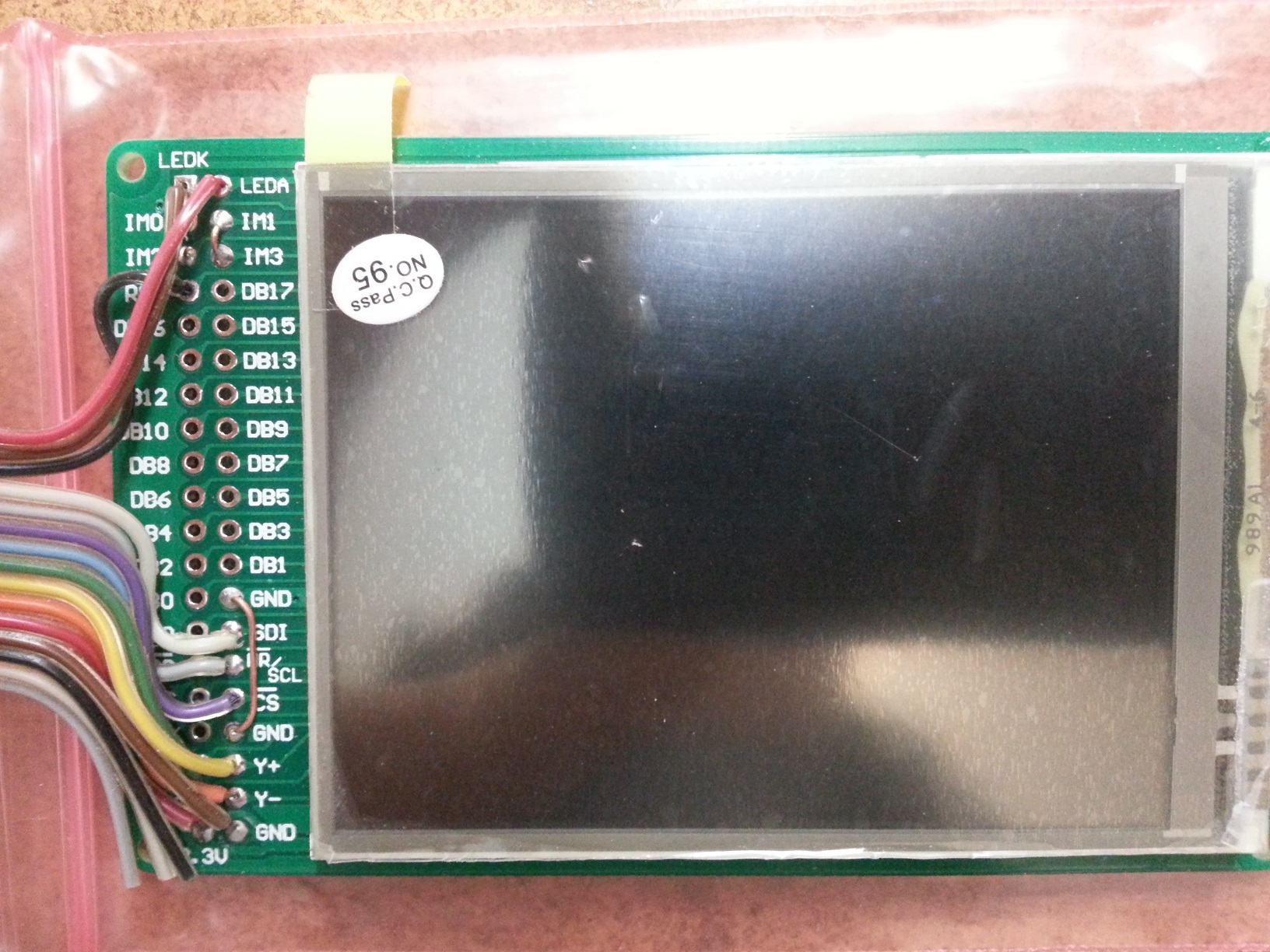
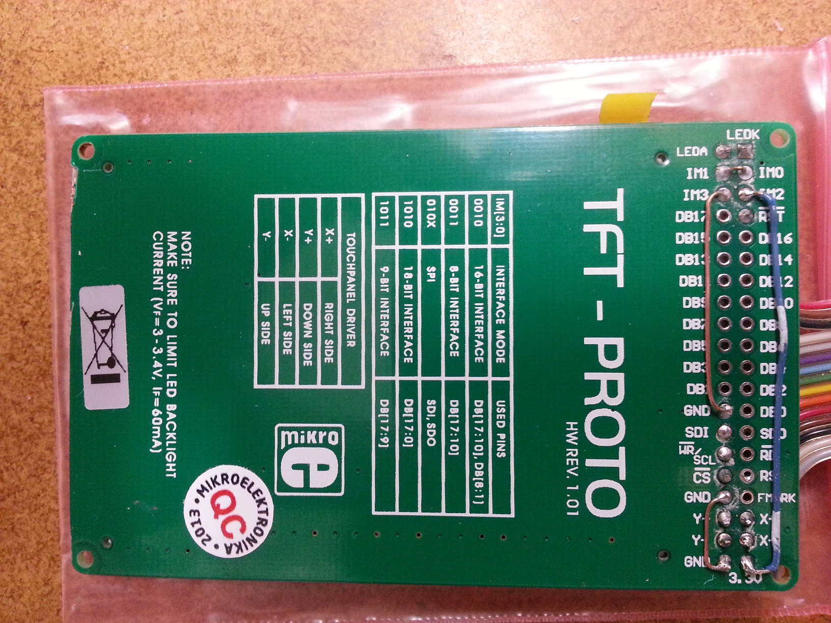
Examples of REV2.00:
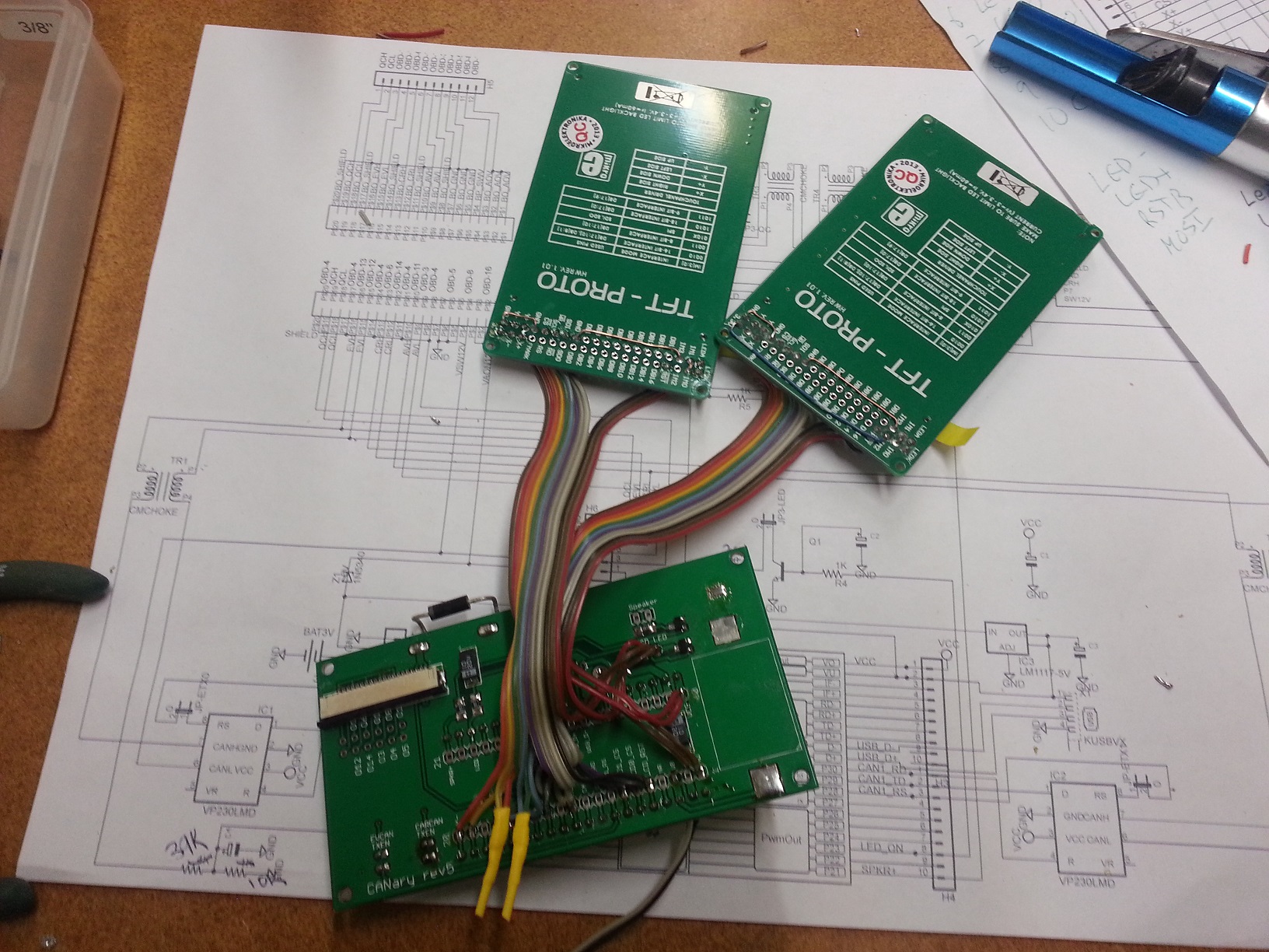
Once the two displays are complete combine all wires except CS0, CS1, X+, X-, Y+, and Y-. Connect X- of the left display to X+ of the right. Similarly connect Y- of the left display to Y+ of the right. Insulate any exposed wires.
2) PCB
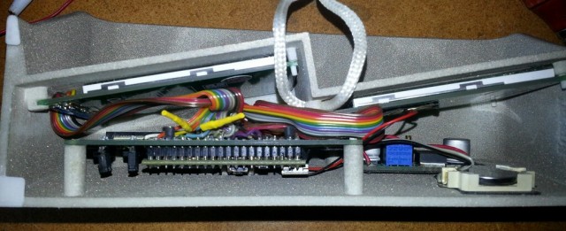
Refer to the schematics to place all the components on the board. If you plan to install into the CANary 3D enclosure, DO NOT install the battery holder or the socket for the mbed and, instead, connect two wires to the VB and GND pads nearby. You will have to install the battery holder against the back wall to avoid interfering with the right-hand display and the mbed will have to be directly soldered. I have not found a socket with a low enough profile to fit in the space provided (depth of enclosure is limited by the space behind the center console). Also, I recommend keeping as much lead as possible on the Zener diode (bending it as shown to clear the back wall). Although it is operating well within parameters, the Zener gets quite hot during extended operation and the leads help dissipate the heat and keep it away from the PCB and other components.Update: Several Zeners have failed resulting in damage to some users boards so I recommend using a DC-DC converter instead to bring the 12V down to 7V.
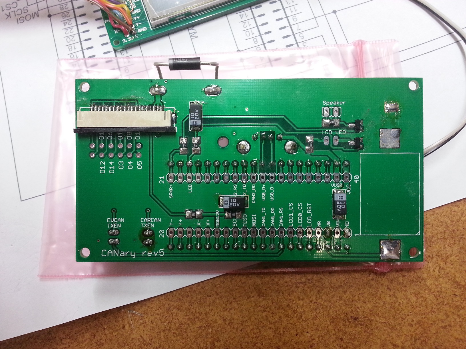
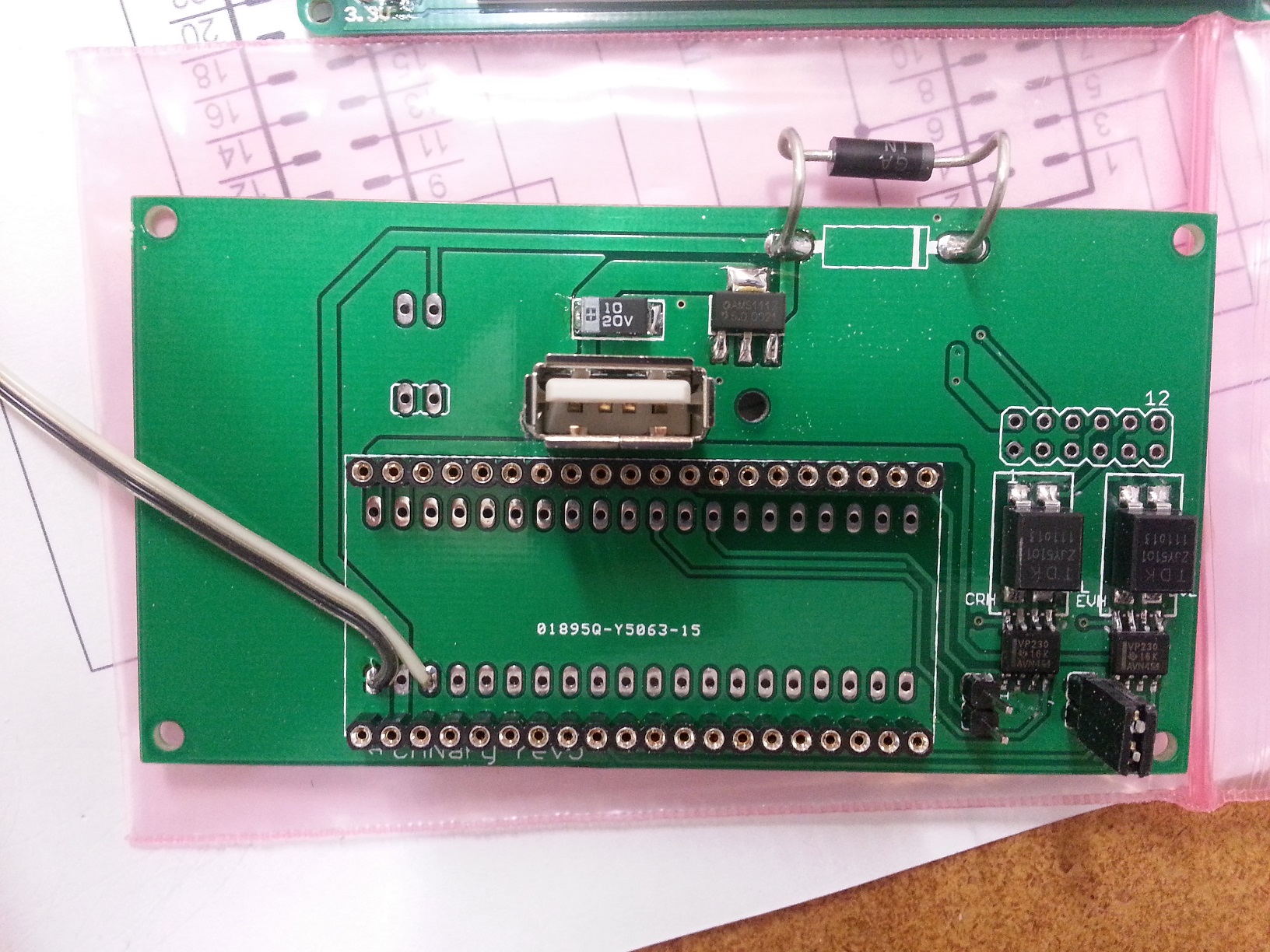
Once the PCB is populated, solder the LCDs to the PCB. CS0 connects to the right display and CS1 connects to the left.
Update:
The Zener diodes tended to fail after a few months so I am recommending removing them and replacing with a DC-DC converter. This will run cooler and waste less energy, too. To install, remove the left display panel to gain access to the Zener. From there, the Zener can be removed and it's pads used to connect to the DC-DC converter. I recommend setting the output voltage on the bench before installing since the trim pot is tricky to reach once installed. Set it to 7V. The input can be connected to the left pad previously occupied by the zener and the output can connect to the right. GND(-) can be connected to the bottom right pad on the 2x6 header below the flex cable connector. Make sure the GND wire lies flat so it doesn't interfere with the connection of the flex cable.
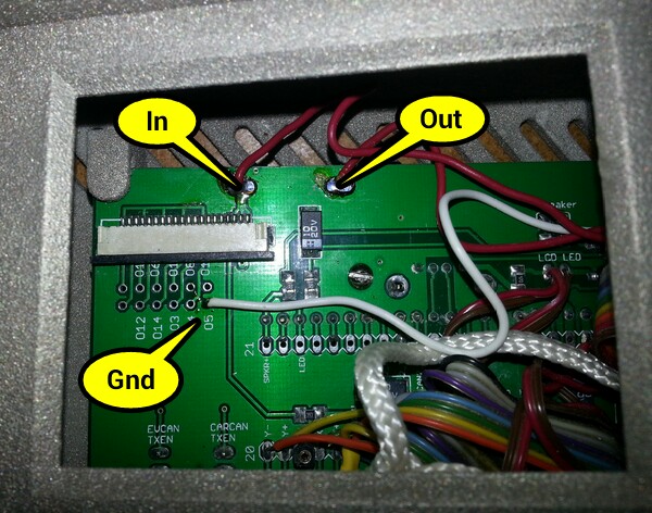
Once soldered in place, the DC-DC converter can easily be mounted to the back wall with double sided tape above the battery holder.
3) Testing
| 1) | First step is to buzz out all connections from the LCDs to the pins in the main board |
| 2) | Next check the touch screen connections. On the main board, place an Ohm meter across X+ and X-. You should read 700 Ohms. Repeat for Y+ and Y-. Then test the resistance from X+ to Y+. With nothing touching the screens, it should read >100K Ohms and <1K when touching either screen. |
| 3) | When all connections are checked, solder in the mbed. Download and install the touch2 program http://mbed.org/users/TickTock/code/touch2/ to test the basic operation of the mbed and touch screens. |
| tips: | |
| Touch screen is sensitive - excess flux on X+,X-,Y+,Y- connection on mbed can result in flakey operation | |
| If touch is not working, double-check the LCD0_CS and LCD1_CS are not swapped. LCD0_CS must connect to the CS of the LCD that has X- & Y- connected to the mbed. LCD1_CS must connect to the CS of the LCD that has X+ & Y+ connected to the mbed. | |
| 4) | Once touch2 works, it is time to connect to the OBD connector. I highly recommend double checking all connections from the OBD to the PCB with the cable in place before connecting to the Leaf. Buzz out all the pins in the OBS to make sure none are shorting to each other, Check that the 12V goes to the Zener (and nothing else) and the switched 12V to the resistor divider (and nothing else). Test the ground connection properly connects to ground and nothing else. |
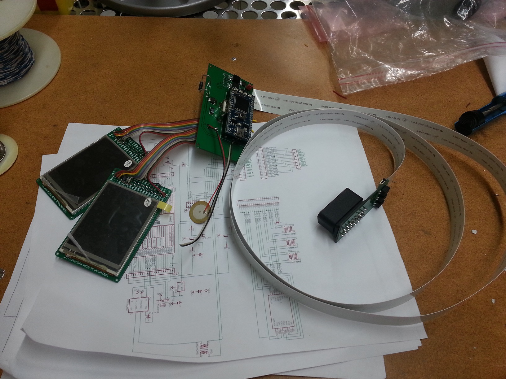
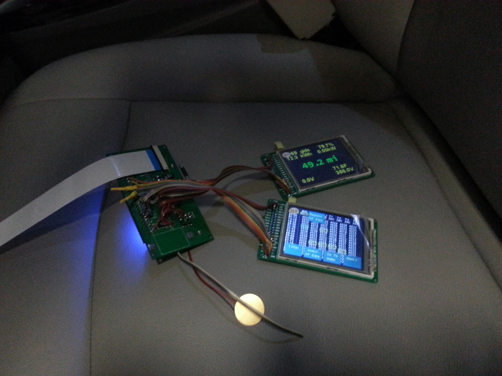
| 5) | Once you are confident there are no shorts or wrong connections from the OBD connector, take a deep breath and plug it into your leaf. Touch2 program should come up and function. Unplug and install the latest CANary firmware. If you have the REV2.00 LCD boards, you will need to edit the precompile.h file in the TOUCH_TFTx2_w9341 library and set USE_ILI9341 to 1. Test all features before installing into the enclosure (gids, cellpair, menu system, logging) since installing and removing from the enclosure is a PITA. |
4) Enclosure
The 3D printer leaves a lot of powder behind - I used a strong spray of water to get it out of all the cracks. The enclosure comes with a rather rough finish. I recommend convincing yourself you like it, then simply lightly sand then paint before assembly. Sanding is very difficult - the nylon is very nicely fused and doesn't want to sand. I tried sandblasting and that didn't work either. I had some limited success with filler and then sanding, but only on the outside - it is too difficult to sand the face.

5) Final Assembly
Make sure you are well rested with lots of patience before attempting assembly. It is a puzzle figuring out how to get both displays and the PCB in place. Enclosure was too expensive for me to keep iterating to optimize for assembly. I ended up snipping the thin display posts shorter and using various tools to push the displays into place. Also, some USB connectors are taller than others. If you have one of the taller ones, you will have to deflect the back wall a bit while inserting the PCB (being careful not to bend the housing) to get it to it's opening in the back wall. Do use a screw in the provided post to secure the PCB as USB insertion will otherwise dislodge it.
I added an additional safety line which wraps around the center post to prevent the enclosure from becoming a projectile in the event of an accident.
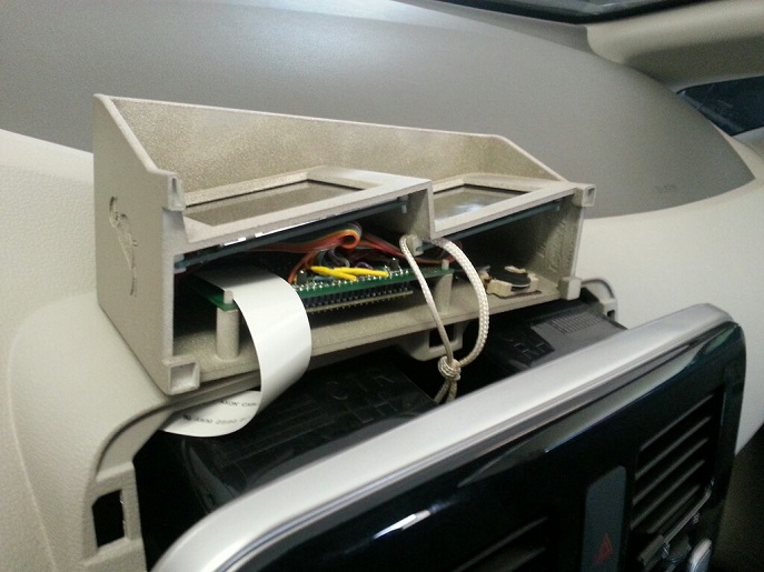 Installed:

Diff: FatFileSystem/ff.h
- Revision:
- 1:9dcd70c32180
- Parent:
- 0:1596b8644523
- Child:
- 2:71b1999a8ea5
--- a/FatFileSystem/ff.h	Mon Nov 19 04:44:11 2012 +0000
+++ /dev/null	Thu Jan 01 00:00:00 1970 +0000
@@ -1,344 +0,0 @@
-/*--------------------------------------------------------------------------/
-/  FatFs - FAT file system module include file  R0.06        (C)ChaN, 2008
-/---------------------------------------------------------------------------/
-/ FatFs module is an experimenal project to implement FAT file system to
-/ cheap microcontrollers. This is a free software and is opened for education,
-/ research and development under license policy of following trems.
-/
-/  Copyright (C) 2008, ChaN, all right reserved.
-/
-/ * The FatFs module is a free software and there is no warranty.
-/ * You can use, modify and/or redistribute it for personal, non-profit or
-/   commercial use without any restriction under your responsibility.
-/ * Redistributions of source code must retain the above copyright notice.
-/
-/---------------------------------------------------------------------------*/
-
-#ifndef _FATFS
-
-#define _MCU_ENDIAN        2
-/* The _MCU_ENDIAN defines which access method is used to the FAT structure.
-/  1: Enable word access.
-/  2: Disable word access and use byte-by-byte access instead.
-/  When the architectural byte order of the MCU is big-endian and/or address
-/  miss-aligned access results incorrect behavior, the _MCU_ENDIAN must be set to 2.
-/  If it is not the case, it can also be set to 1 for good code efficiency. */
-
-#define _FS_READONLY    0
-/* Setting _FS_READONLY to 1 defines read only configuration. This removes
-/  writing functions, f_write, f_sync, f_unlink, f_mkdir, f_chmod, f_rename,
-/  f_truncate and useless f_getfree. */
-
-#define _FS_MINIMIZE    0
-/* The _FS_MINIMIZE option defines minimization level to remove some functions.
-/  0: Full function.
-/  1: f_stat, f_getfree, f_unlink, f_mkdir, f_chmod, f_truncate and f_rename are removed.
-/  2: f_opendir and f_readdir are removed in addition to level 1.
-/  3: f_lseek is removed in addition to level 2. */
-
-#define    _USE_STRFUNC    0
-/* To enable string functions, set _USE_STRFUNC to 1 or 2. */
-
-#define    _USE_MKFS    1
-/* When _USE_MKFS is set to 1 and _FS_READONLY is set to 0, f_mkfs function is
-/  enabled. */
-
-#define _DRIVES        4
-/* Number of logical drives to be used. This affects the size of internal table. */
-
-#define    _MULTI_PARTITION    0
-/* When _MULTI_PARTITION is set to 0, each logical drive is bound to same
-/  physical drive number and can mount only 1st primaly partition. When it is
-/  set to 1, each logical drive can mount a partition listed in Drives[]. */
-
-#define _USE_FSINFO    0
-/* To enable FSInfo support on FAT32 volume, set _USE_FSINFO to 1. */
-
-#define    _USE_SJIS    1
-/* When _USE_SJIS is set to 1, Shift-JIS code transparency is enabled, otherwise
-/  only US-ASCII(7bit) code can be accepted as file/directory name. */
-
-#define    _USE_NTFLAG    1
-/* When _USE_NTFLAG is set to 1, upper/lower case of the file name is preserved.
-/  Note that the files are always accessed in case insensitive. */
-
-
-#include "integer.h"
-
-#ifdef __cplusplus
-extern "C" {
-#endif
-
-/* Definitions corresponds to multiple sector size (not tested) */
-#define    S_MAX_SIZ    512U            /* Do not change */
-#if S_MAX_SIZ > 512U
-#define    SS(fs)    ((fs)->s_size)
-#else
-#define    SS(fs)    512U
-#endif
-
-
-/* File system object structure */
-typedef struct _FATFS {
-    WORD    id;                /* File system mount ID */
-    WORD    n_rootdir;        /* Number of root directory entries */
-    DWORD    winsect;        /* Current sector appearing in the win[] */
-    DWORD    sects_fat;        /* Sectors per fat */
-    DWORD    max_clust;        /* Maximum cluster# + 1 */
-    DWORD    fatbase;        /* FAT start sector */
-    DWORD    dirbase;        /* Root directory start sector (cluster# for FAT32) */
-    DWORD    database;        /* Data start sector */
-#if !_FS_READONLY
-    DWORD    last_clust;        /* Last allocated cluster */
-    DWORD    free_clust;        /* Number of free clusters */
-#if _USE_FSINFO
-    DWORD    fsi_sector;        /* fsinfo sector */
-    BYTE    fsi_flag;        /* fsinfo dirty flag (1:must be written back) */
-    BYTE    pad2;
-#endif
-#endif
-    BYTE    fs_type;        /* FAT sub type */
-    BYTE    csize;            /* Number of sectors per cluster */
-#if S_MAX_SIZ > 512U
-    WORD    s_size;            /* Sector size */
-#endif
-    BYTE    n_fats;            /* Number of FAT copies */
-    BYTE    drive;            /* Physical drive number */
-    BYTE    winflag;        /* win[] dirty flag (1:must be written back) */
-    BYTE    pad1;
-    BYTE    win[S_MAX_SIZ];    /* Disk access window for Directory/FAT */
-} FATFS;
-
-
-/* Directory object structure */
-typedef struct _DIR {
-    WORD    id;            /* Owner file system mount ID */
-    WORD    index;        /* Current index */
-    FATFS*    fs;            /* Pointer to the owner file system object */
-    DWORD    sclust;        /* Start cluster */
-    DWORD    clust;        /* Current cluster */
-    DWORD    sect;        /* Current sector */
-} FATFS_DIR;
-
-
-/* File object structure */
-typedef struct _FIL {
-    WORD    id;                /* Owner file system mount ID */
-    BYTE    flag;            /* File status flags */
-    BYTE    csect;            /* Sector address in the cluster */
-    FATFS*    fs;                /* Pointer to the owner file system object */
-    DWORD    fptr;            /* File R/W pointer */
-    DWORD    fsize;            /* File size */
-    DWORD    org_clust;        /* File start cluster */
-    DWORD    curr_clust;        /* Current cluster */
-    DWORD    curr_sect;        /* Current sector */
-#if _FS_READONLY == 0
-    DWORD    dir_sect;        /* Sector containing the directory entry */
-    BYTE*    dir_ptr;        /* Ponter to the directory entry in the window */
-#endif
-    BYTE    buffer[S_MAX_SIZ];    /* File R/W buffer */
-} FIL;
-
-
-/* File status structure */
-typedef struct _FILINFO {
-    DWORD fsize;            /* Size */
-    WORD fdate;                /* Date */
-    WORD ftime;                /* Time */
-    BYTE fattrib;            /* Attribute */
-    char fname[8+1+3+1];    /* Name (8.3 format) */
-} FILINFO;
-
-
-
-/* Definitions corresponds to multi partition */
-
-#if _MULTI_PARTITION != 0    /* Multiple partition cfg */
-
-typedef struct _PARTITION {
-    BYTE pd;    /* Physical drive # (0-255) */
-    BYTE pt;    /* Partition # (0-3) */
-} PARTITION;
-extern
-const PARTITION Drives[];            /* Logical drive# to physical location conversion table */
-#define LD2PD(drv) (Drives[drv].pd)    /* Get physical drive# */
-#define LD2PT(drv) (Drives[drv].pt)    /* Get partition# */
-
-#else                        /* Single partition cfg */
-
-#define LD2PD(drv) (drv)        /* Physical drive# is equal to logical drive# */
-#define LD2PT(drv) 0            /* Always mounts the 1st partition */
-
-#endif
-
-
-/* File function return code (FRESULT) */
-
-typedef enum {
-    FR_OK = 0,            /* 0 */
-    FR_NOT_READY,        /* 1 */
-    FR_NO_FILE,            /* 2 */
-    FR_NO_PATH,            /* 3 */
-    FR_INVALID_NAME,    /* 4 */
-    FR_INVALID_DRIVE,    /* 5 */
-    FR_DENIED,            /* 6 */
-    FR_EXIST,            /* 7 */
-    FR_RW_ERROR,        /* 8 */
-    FR_WRITE_PROTECTED,    /* 9 */
-    FR_NOT_ENABLED,        /* 10 */
-    FR_NO_FILESYSTEM,    /* 11 */
-    FR_INVALID_OBJECT,    /* 12 */
-    FR_MKFS_ABORTED        /* 13 */
-} FRESULT;
-
-
-
-/*-----------------------------------------------------*/
-/* FatFs module application interface                  */
-
-FRESULT f_mount (BYTE, FATFS*);                        /* Mount/Unmount a logical drive */
-FRESULT f_open (FIL*, const char*, BYTE);            /* Open or create a file */
-FRESULT f_read (FIL*, void*, UINT, UINT*);            /* Read data from a file */
-FRESULT f_write (FIL*, const void*, UINT, UINT*);    /* Write data to a file */
-FRESULT f_lseek (FIL*, DWORD);                        /* Move file pointer of a file object */
-FRESULT f_close (FIL*);                                /* Close an open file object */
-FRESULT f_opendir (FATFS_DIR*, const char*);                /* Open an existing directory */
-FRESULT f_readdir (FATFS_DIR*, FILINFO*);                    /* Read a directory item */
-FRESULT f_stat (const char*, FILINFO*);                /* Get file status */
-FRESULT f_getfree (const char*, DWORD*, FATFS**);    /* Get number of free clusters on the drive */
-FRESULT f_truncate (FIL*);                            /* Truncate file */
-FRESULT f_sync (FIL*);                                /* Flush cached data of a writing file */
-FRESULT f_unlink (const char*);                        /* Delete an existing file or directory */
-FRESULT    f_mkdir (const char*);                        /* Create a new directory */
-FRESULT f_chmod (const char*, BYTE, BYTE);            /* Change file/dir attriburte */
-FRESULT f_utime (const char*, const FILINFO*);        /* Change file/dir timestamp */
-FRESULT f_rename (const char*, const char*);        /* Rename/Move a file or directory */
-FRESULT f_mkfs (BYTE, BYTE, WORD);                    /* Create a file system on the drive */
-#if _USE_STRFUNC
-#define feof(fp) ((fp)->fptr == (fp)->fsize)
-#define EOF -1
-int fputc (int, FIL*);                                /* Put a character to the file */
-int fputs (const char*, FIL*);                        /* Put a string to the file */
-int fprintf (FIL*, const char*, ...);                /* Put a formatted string to the file */
-char* fgets (char*, int, FIL*);                        /* Get a string from the file */
-#endif
-
-/* User defined function to give a current time to fatfs module */
-
-DWORD get_fattime (void);    /* 31-25: Year(0-127 org.1980), 24-21: Month(1-12), 20-16: Day(1-31) */
-                            /* 15-11: Hour(0-23), 10-5: Minute(0-59), 4-0: Second(0-29 *2) */
-
-
-
-/* File access control and file status flags (FIL.flag) */
-
-#define    FA_READ                0x01
-#define    FA_OPEN_EXISTING    0x00
-#if _FS_READONLY == 0
-#define    FA_WRITE            0x02
-#define    FA_CREATE_NEW        0x04
-#define    FA_CREATE_ALWAYS    0x08
-#define    FA_OPEN_ALWAYS        0x10
-#define FA__WRITTEN            0x20
-#define FA__DIRTY            0x40
-#endif
-#define FA__ERROR            0x80
-
-
-/* FAT sub type (FATFS.fs_type) */
-
-#define FS_FAT12    1
-#define FS_FAT16    2
-#define FS_FAT32    3
-
-
-/* File attribute bits for directory entry */
-
-#define    AM_RDO    0x01    /* Read only */
-#define    AM_HID    0x02    /* Hidden */
-#define    AM_SYS    0x04    /* System */
-#define    AM_VOL    0x08    /* Volume label */
-#define AM_LFN    0x0F    /* LFN entry */
-#define AM_DIR    0x10    /* Directory */
-#define AM_ARC    0x20    /* Archive */
-
-
-
-/* Offset of FAT structure members */
-
-#define BS_jmpBoot            0
-#define BS_OEMName            3
-#define BPB_BytsPerSec        11
-#define BPB_SecPerClus        13
-#define BPB_RsvdSecCnt        14
-#define BPB_NumFATs            16
-#define BPB_RootEntCnt        17
-#define BPB_TotSec16        19
-#define BPB_Media            21
-#define BPB_FATSz16            22
-#define BPB_SecPerTrk        24
-#define BPB_NumHeads        26
-#define BPB_HiddSec            28
-#define BPB_TotSec32        32
-#define BS_55AA                510
-
-#define BS_DrvNum            36
-#define BS_BootSig            38
-#define BS_VolID            39
-#define BS_VolLab            43
-#define BS_FilSysType        54
-
-#define BPB_FATSz32            36
-#define BPB_ExtFlags        40
-#define BPB_FSVer            42
-#define BPB_RootClus        44
-#define BPB_FSInfo            48
-#define BPB_BkBootSec        50
-#define BS_DrvNum32            64
-#define BS_BootSig32        66
-#define BS_VolID32            67
-#define BS_VolLab32            71
-#define BS_FilSysType32        82
-
-#define    FSI_LeadSig            0
-#define    FSI_StrucSig        484
-#define    FSI_Free_Count        488
-#define    FSI_Nxt_Free        492
-
-#define MBR_Table            446
-
-#define    DIR_Name            0
-#define    DIR_Attr            11
-#define    DIR_NTres            12
-#define    DIR_CrtTime            14
-#define    DIR_CrtDate            16
-#define    DIR_FstClusHI        20
-#define    DIR_WrtTime            22
-#define    DIR_WrtDate            24
-#define    DIR_FstClusLO        26
-#define    DIR_FileSize        28
-
-
-
-/* Multi-byte word access macros  */
-
-#if _MCU_ENDIAN == 1    /* Use word access */
-#define    LD_WORD(ptr)        (WORD)(*(WORD*)(BYTE*)(ptr))
-#define    LD_DWORD(ptr)        (DWORD)(*(DWORD*)(BYTE*)(ptr))
-#define    ST_WORD(ptr,val)    *(WORD*)(BYTE*)(ptr)=(WORD)(val)
-#define    ST_DWORD(ptr,val)    *(DWORD*)(BYTE*)(ptr)=(DWORD)(val)
-#elif _MCU_ENDIAN == 2    /* Use byte-by-byte access */
-#define    LD_WORD(ptr)        (WORD)(((WORD)*(volatile BYTE*)((ptr)+1)<<8)|(WORD)*(volatile BYTE*)(ptr))
-#define    LD_DWORD(ptr)        (DWORD)(((DWORD)*(volatile BYTE*)((ptr)+3)<<24)|((DWORD)*(volatile BYTE*)((ptr)+2)<<16)|((WORD)*(volatile BYTE*)((ptr)+1)<<8)|*(volatile BYTE*)(ptr))
-#define    ST_WORD(ptr,val)    *(volatile BYTE*)(ptr)=(BYTE)(val); *(volatile BYTE*)((ptr)+1)=(BYTE)((WORD)(val)>>8)
-#define    ST_DWORD(ptr,val)    *(volatile BYTE*)(ptr)=(BYTE)(val); *(volatile BYTE*)((ptr)+1)=(BYTE)((WORD)(val)>>8); *(volatile BYTE*)((ptr)+2)=(BYTE)((DWORD)(val)>>16); *(volatile BYTE*)((ptr)+3)=(BYTE)((DWORD)(val)>>24)
-#else
-#error Do not forget to set _MCU_ENDIAN properly!
-#endif
-
-#ifdef __cplusplus
-};
-#endif
-
-#define _FATFS
-#endif /* _FATFS */
