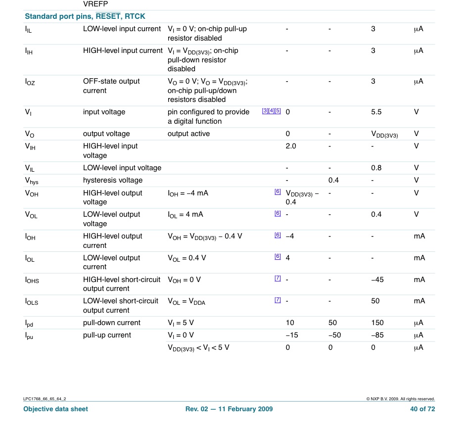
I believe the specification for digital output current shown on this page is not exactly correct...
http://mbed.org/handbook/mbed-NXP-LPC1768
Please see the attached and note the following: The high level output voltage and low level output voltage are both with a 4 MILLIAMP TEST CURRENT. The 50 milliamp spec is a short circuit current! That means that the chip will not hold its logic level at these currents! In other words, if the logic is trying to put out a "1" and you short it to ground, you will get a maximum current of 45 mA. if the logic is trying to put out a "0" and you short it to the rail, you will get a maximum current of 50 mA into the chip.
The only way we can find the actual output current is by testing. What we want to know is, how much current can we draw in the high state and stay above a typical 2.0 Volt input threshold. And how much current can we put into the device in the low state and stay below a typical 0.8 Volt input threshold.
I'm pretty sure neither of these currents is anywhere near 50 milliamps! Hope this helps. By the way, MBED is still great.