You are viewing an older revision! See the latest version
SPI communication with external ADC MCP3
This is my code for interacting with external ADCs called MCP3208 and MCP3204
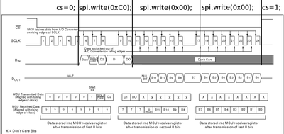
- DEVICE INFO: in my case it is a MCP3208, which recives 5 bits and sends back 12 bits
- SENDING: it has 2 bits for mode selection and the other 3 for selecting the right analog sensor
- RECIVE: first it sends 2 null bits which I just ignore and then it sends 12 bits which is the analog sensor reading
- MORE INFO: for the communication I use the built in registers for SPI communication, the SPI protocoll is very simple there is the chip select pin which identifies the chip we want to communicate to and there is the clock which gives the chip info when we are sending the next bit and finally there are the mosi and miso pins which are for incoming and outgoing data
- MANUAL: the chips manuals can be found http://www.ereshop.com/shop/free/MCP3208.pdf and more about SPI
- PS: in this example I use a specific analog sensor, when you want to use another just change the 3 bits used for selecting the analog sensor
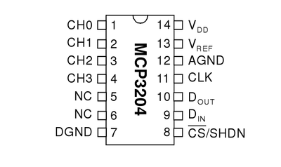
Quote:
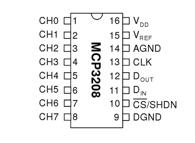
The pins for the MCP3208 and MCP3204
Quote:
Soldering the circuit board for the MCP3208 or MCP3204 coming soon ...
Quote:
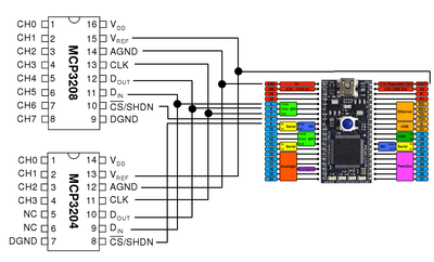
Connecting mbed to the MCP3208 or MCP3204 to be updated ...
Quote:
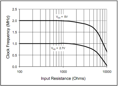
Which clock to use
Quote:
Communication
#include "mbed.h"

SPI spi(p5, p6, p7); // mosi(out), miso(in), sclk(clock)
DigitalOut cs(p8); // cs (the chip select signal)

Serial pc(USBTX, USBRX); // tx, rx ( the usb serial communication )

int main() {
    // Setup the spi for 7 bit data, high steady state clock,
    // second edge capture, with a 1MHz clock rate
    spi.format(7,0);
    spi.frequency(1000000);

    // notify the user that we are starting with the ADC communication
    pc.printf("Starting ADC interaction\n");

    // lets just do this forever
    while (1) {

        // Select the device by seting chip select low
        cs = 0;

        // sending the 5 bits + 2 bits to ignore the null bits
        // coming from the device, so the data that is sent is 1100000
        spi.write(0xC0);

        // now the device sends back the readings 12 bits, 7 bits at a time
        int adc2 = spi.write(0x00);
        int adc3 = spi.write(0x00);

        // now we have to mask out the right bits
        // 31 in binary is 00011111
        int mask = 31;

        // we only want the 5 bits from the second reading not 7 as recived
        adc3 = mask & adc3;

        // we shift and or the result together
        int value = ( adc2 << 5 ) | adc3;

        // and voila we have the value and we can print it for the user
        pc.printf("WHOAMI register2 = %u\n", value);

        // Deselect the device
        cs = 1;

        // delay some time before reading again
        wait(1);
    }
}
