Prototype To Hardware
Introduction
There has been a lot of questions in the forum about just how easy it would be to move forward from an mbed Microcontroller to actually use the target MCU (NXP LPC1768), avoiding the need to design in £30+ modules
Before showing just how easy it can be, there are a couple of points to make clear:
- You can use the mbed libraries commercially for free, on an unsupported as-is basis
- The mbed compiler generates a raw binary targeting the MCU, there is no bootloader magic going on in the binary
- The binary runs on the LPC1768 bare metal, there is no runtime environment
- The only magic taking place on the mbed Microcontroller is the "mbed Interface" - It's not actually all that magic, it is just a USB device that can program the raw binary into the LPC1768s flash memory So with that in mind it should be clear that if you wish to take your design to the next stage you can spin your own PCB, solder down the LPC1768 and reuse the binary you made with your mbed Microcontroller prototype, you can.
The purpose is to show you how you can get your binary into the LPC1768 on your own PCB, and what other things you can do.
mbed Prototype
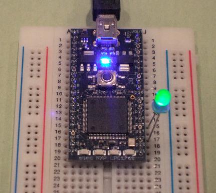
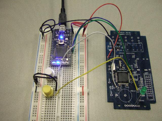
The first thing to do is write a (very) simple program that prints "hello world!" to hyperterminal, and flashes an LED forever. I'll do this on an mbed module first, and then attempt to port it to an LPC1768 on an custom PCB.
I'm driving both ends of the LED as I have a PCB for an LPC1768 that i can port the binary to as an experiment, and doing the double ended driving is the simplest way.
Here is the code :
#include "mbed.h"

Serial pc (USBTX,USBRX);

DigitalOut ledA(p26);
DigitalOut ledK(p24);

int main() {

    pc.printf("Hello world!\n");

    ledK = 0;

    while(1) {
        ledA = 1;
        wait(0.2);
        ledA = 0;
        wait(0.2);
    }
}
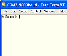
Here is the result :
| Teraterm Output | The hardware |
|---|---|
 |  |
Custom PCB
I have a PCB that my brother has spun for an mbed project (programmable access controller). I have put down an LPC1768 and just enough passive to get it running. We'll now see the steps to go through to get the binary that was developed on the mbed prototype running on this LPC1768.
Programming the LPC1768 (theory)
There are two ways to get a binary into the LPC1768; JTAG and the In System Programming (ISP) over a UART using the LPC1768s built-in serial bootloader.
The JTAG method is what you will find on a lot of development boards. It offers many additional features (debug, semihosting, etc) as well as just the ability to load the binary image. Using the JTAG port requires a JTAG "wiggler" to drive the JTAG interface, and some software that knows how to communicate over JTAG and load the binary.
The other method is ISP using the LCP1768 bootlaoder, which relies on a simple strategy:
- Pull nReset low to put the LPC1768 into reset
- Pull the ISP pin (P0.14) low, to indicate the ISP is intended
- Pull nReset high. The LPC1768 comes out of reset and samples the ISP pin. If it is low, the bootloader runs
- The bootloader communicates over a serial connection on UART0: TXD0 = p0.2 = pin 98 ; RXD0 = p0.3 - pin 99
- With a level shifter you can quite happily connect to it from your computers COM port and use teraterm to type commands to it and see the reply, or use some software to communicates and download binaries. The bootloader software uses a series of commands to query the device status, erase, transfer and program binary data to the LPC1768's flash memory. The process is well documented :
- http://www.nxp.com/documents/user_manual/UM10360.pdf
- Chapter 32, Page 605 onwards it's all there
Life is too short to craft your own way to transferring data by talking to the LPC1768's built in bootloader. Thankfully there are some great apps out there which will do it for you. For the purpose of this example I am using Flash Magic:
- www.flashmagictool.com
Programming the LPC1768 (practice)
The first stop is to get the LPC1768 on the custom PCB into ISP mode, and communicate with it.
Communicating with the LPC1768
To bridge control the pins, and bridge the bootloader serial port to my PC, I will use my mbed as a serial passthrough and to drive the ISP and nReset pins. I'll refer to this arrangement as mbedISP.
- Use GPIO pins (p29,p30) of my mbed to manipulate the nReset and ISP pins on the custom PCB
- Use a serial port (p28,p27) to connect to the bootloader serial port on the LPC1768
- Use the USB serial port to communicate with the PC, and simply pass characters back and forth between the LPC1768 and the PC via the mbed - Think of it as USB -> RS232+Levelshifter ... and then some.. As the nReset and ISP pins have pullups, they should be driven with an open collector. I will mimic this by using a DigitalInOut, driving as an output of value 0, or as an input with no pull-up.
#include "mbed.h"

DigitalOut led1(LED1);
DigitalOut led2(LED2);

Serial pc (USBTX,USBRX);
Serial target (p28,p27);

// We'll drive this low, and then set the as inputs
// this mimics an open collector style ouput
DigitalInOut reset (p29);
DigitalInOut isp   (p30);

int main() {

    pc.baud(19200);
    target.baud(19200);

    // ISP Input with pullup
    isp.input();
    isp.mode(PullUp);

    // pulse reset low
    reset.output();
    reset = 0;
    wait (0.01);

    // reset input, with pullup
    reset.input();
    reset.mode(PullUp);

    while (!pc.readable()) {}

    // pull ISP and nReset low
    reset.output();
    isp.output();
    reset = 0;
    isp = 0;

    wait (0.1);

    // Bring target out of reset
    reset.input();
    reset.mode(PullUp);

    wait (0.1);

    while (1) {

        if (pc.readable()) {
            target.putc(pc.getc());
            led1 = !led1;
        }

        if (target.readable()) {
            pc.putc(target.getc());
            led2 = !led2;
        }

    }
}
Below is a wiring table of the four pins to go from the mbed to the LPC1768. the two devices must also share a common ground.
| mbed | LPC1768 |
| p30 (isp) | P2.10 (pin 53) |
| p29 (reset) | nReset (pin 17) |
| p28 (TX) | RXD0 (pin 99) |
| p27 (RX) | TXD0 (pin 98) |
Now to try it out:
- Wire the custom PCB to the mbed.
- Build the binary of the code shown.
- Install the serial drivers for my mbed (see http://mbed.org/handbook/SerialPC for more details)
- Run it and see what happens
I should be able to type in ISP commands from the LPC1768 manual listed above, and get the expected response. I'll start simple by sending the "?" character which is for autobaud detection - the LPC1768 should reply "Synchronized".
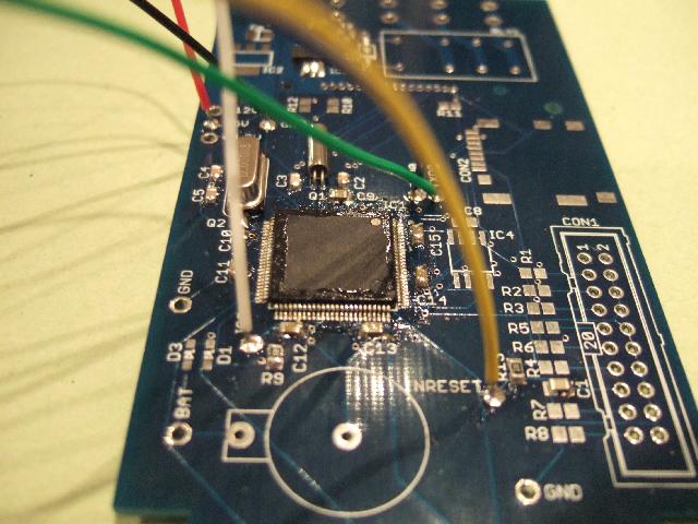 | 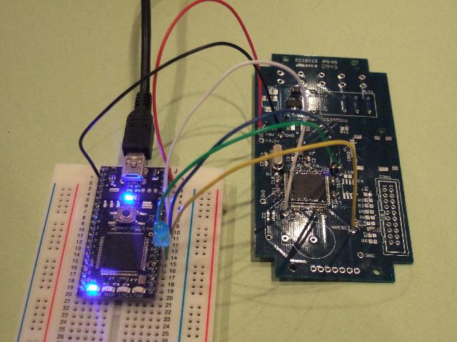 |
| Connections to the Custom PCB - A header might be better! | Hooked up to mbedISP |
First attempt, and it works better than I'd hoped for. I sent the "?", and immediately got "Synchronized".
I followed the manual, so sent back "Synchronized", recieved "OK", sent back "OK", and I was then free to play.
I kept it simple, I run commands J (to get the part ID) and K (to get the booloader version.
- Part ID 369162533
- Bootloader v3.3
Downloading a binary
I can now communicate with the LPC1768 in bootloader mode, so it is now time to see if I can use FlashMagic to do the comms for me.
I have flash magic installed, it is a nice looking tool, but the first thing I notice is that it only support .HEX files, whereas the mbed compiler only generates .BIN files.
One quick google later, and a rather useful page appears about a BIN2HEX utility.
note
BIN2HEX does not work on 64-bit versions on windows.
- http://www.keil.com/download/docs/113.asp - This has some usage information, but also contains a link to where you can download the windows executable
- http://www.hex2bin.com/bin2hex - Click the link and the download starts!
I download the zipfile, extract it into C:\prototype then copy the binary I made earlier "prototype.bin". The first thing I notice is that when I try to convert this, it says it can't open the file, even though I autocompleted the file name. I think this has something to dowith 8.3 files names, so I rename my binary to "ptype.bin" and it works a treat.
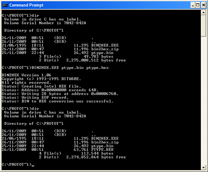
I now have "ptype.hex" to load into Flash Magic, so lets go back to Flash Magic...
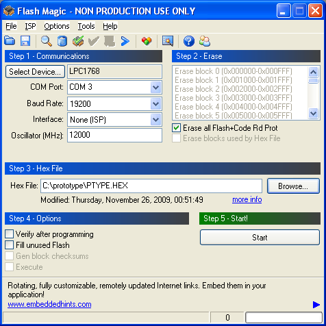
Flash Magic loads and there are a few things to configure, namely :
- Device : LPC1768
- COM port : COM3 (my mbedISP)
- Baud rate : This was set in the mbedISP code as 19200
- Hex file : Load the one I just created.
Before I try and download the binary, I notice there are some options, like read Device ID, so as a test i'll try that first. Bingo. It works! :
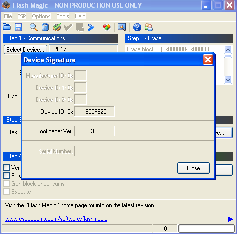
The interesting thing here is that it reports the bootloader version I got earlier and the Device ID as a hex number (0x1600f925). before I got 369162533 as a decimal... which happen to match.
Great, I am clearly communicating happily with the LPC1768 from Flash Magic.
Nothing left but to download... Phut!
It is complaining that the device signature does not match the expected. On closer inspection, it looks like I have actually soldered down an LPC2368 not an LPC1768 - the danger of having two almost identical parts to hand. No worries though. I go back to the compiler, and rebuild "prototype.bin", this time selecting the LPC2368 target - You've got to love the way you can choose which architecture to build your binary for with a dropdown menu. Instead of saving it to my mbed, I put it in "c\prototype" saving it as "ptype.bin", go back to my Command Prompt ("DOS", for the over 25's), and re-run BIN2HEX.
I reset the mbedISP so that it again awaiting the first character, and go back to Flash Magic, select the target as LPC2368 and try again.
Hurrah! Flash Magic runs through cleanly with no reported problems. I insert the LED into the two adjacent holes that connect to LPC1768 pins 74,75 (DIP pins p24,p26)....
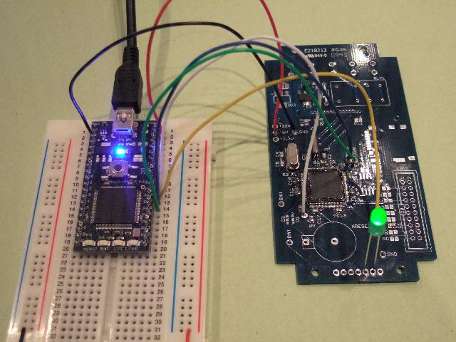 | |
| A picture of the setup | Just to prove it's working! |
The next thing you'll have noticed is that when prototyping we relied on the USB serial port for printing "Hello world". On the mbed microcontroller, when you print to USB, what you are actually doing is printing to UART0; this connects to the "mbed Interface" which routes it over USB. Now we are on a custom PCB, we dont have the interface to do that, but what we now have is printf coming out on the UART we're using for bootload. This means that any printfs in your prototype code now come out of your LPC1768 UART0, into the mbed ISP and get routed over it's USB serial. In short, you still have printf debug over USB :-)
We're not quite there
So while playing with it, I have noticed a few things that are annoying, or could work better. The mbedISP controlling ISP and nReset seemed like a good idea, but it really isnt, for a few reasons;
- the while(1) loop doesn't know download has stopped, so I have to reset manually. Could be solved with a timeout, but it still feels likeI don't have the control I want.
- My program is doing "printf" out of the UART as the first thing. When the mbedISP, goes through some reset cycles half this this gets printed, which interferes with the ISP communication. This means I can't ISP program it again easily, which means I cant erase it to remove the problem. I had to do some manual ISP in Teraterm to recover :-(
- Once I have reset, the only way to see output it to send a character first (the program is waiting for a "?" from the host before resetting) and going into ISP mode The simplifications needed seem obvious. Make ISP and nReset manual with a couple of push buttons, and turn mbedISP into a simple serial passthrough. To put the LPC1768 in ISP mode, press and release nReset while ISP is held low.
This is the code and setup for mbedISP
#include "mbed.h"

DigitalOut led1(LED1);
DigitalOut led2(LED2);

Serial pc (USBTX,USBRX);
Serial target (p28,p27);


int main() {

    pc.baud(9600);
    target.baud(9600);

    while (1) {

        if (pc.readable()) {
            target.putc(pc.getc());
            led1 = !led1;
        }

        if (target.readable()) {
            pc.putc(target.getc());
            led2 = !led2;
        }

    }
}
Optimisations
This is all working very nicely. Now if have access to the nReset and ISP, I can reset the LPC1768 as much as I want, and put it into ISP as I want.
The only think to look at now is the speed - it takes forever to download (45 seconds). So if I now chage my prototype program to set the serial port to say 115,200bps and set the mbedISP to do run both serial ports at this speed, we might be able to reduce the programming time, and make printf faster.
Lets try...
Wheesh... I can read the Device ID of the part at 115,200.. it is rather responsive :-)
Wheesh... Downloading in about 6 seconds
The prototype app is now printing "Hello world" pretty quickly too!
Lets see if it will go faster (230,400)... Phut... no.. looks like 115,200bps is as fast as we can go. Still, thats not too shabby.
Hardware convention To connect to an LPC1768 on a custom PCB we need to connect to:
- Gnd
- ISP (P2.10)
- nReset
- TXD0
- RXD0
I think we should assume that the target system must provide it's own power. This is a safe way to do it as then we dont have to make any assumptions about it's voltage or current consumption.
I have had a quick look around for a standard ISP pin header (I thought there was a 2x3 one at some point). If not I'd like to propose that anyone wishing to expose an ISP interface does so with a 1x5 0.1" header with the following pinout:
- Gnd
- ISP (P2.10)
- nReset
- TXD0
- RXD0
That way, it would be easy to make a little programming breakout board to post up on BatchPCB.
Conclusion
I think this experiment has proven that it is fairly straight forward to program an LPC1768 (or LPC2368, as it turns out) via ISP when it is on your own PCB.
I hope this page will serve as a good reference of how to go about this, please leave comments and feedback, and i'll tweek this page up as needed.
In the mean time, there are some useful resources :
- http://www.flashmagictool.com - The ISP programming software
- http://www.hex2bin.com/bin2hex - The utility to convert .BIN files into .HEX files
- http://mbed.org/users/chris/programs/16mhsw - The mbedISP program. It's simple enough, but here is is anyway.