Transistor Switch
Transistor Switch
collector current is proportionally limited by its base current => current controlled switch
operating between cutoff and saturation
current move against direction of emitter arrow
advantage: small switch controlling high current load, true amplifier relatively low power signal to control a relatively large amount of power (actual power is from a source not the transistor signal current)
phototransistor which transitions when light in the near-infrared range (700nm - 1100nm) is detected by the phototransistor
called amplifier bz small current controlling large current
disconnected as the light is used to enable the current flow through the phototransistor. In some instances the base may be biased to set the required operating point.
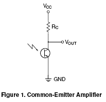
Common Emitter transition from high state to a low state
Output created by connecting a resistor between supply and collector.
The output voltage is read at the terminal of the collector.
For three pin: base is input, collector is output, and emitter is common to both eg (attached to ground)

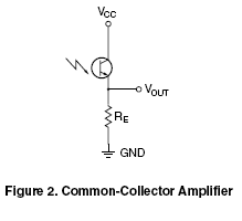
Common Collector transition from low state to a high state
output created by connectina a resistor between te emitter pin of the component and ground
output read at emitter terminal

Amplifier circuit load resistor is used to set the operation mode when no base connection is given
resistor value of 5kΩ or higher is adequate to
operate the phototransistor in the switch mode.The high
level output voltage in the switching mode should equal the
supply voltage. The low level output voltage in the switching
mode should be less than 0.8 Volts.
"Linear" or Active Mode the phototransistor generates a
response proportional to the light received by the component
up to a certain light level. When the amount of light surpasses
that level, the phototransistor becomes saturated and
the output will not increase even as the light level increases. used for light comparison
VCC > RL * ICC
Switch Mode phototransistor will either be
”off” (cut-off) or ”on” (saturated) in response to the light. for detecting objects, sending data or encoder sensing
VCC < RL * ICC
Links
Design Fundamentals for Phototransistor Circuits: http://www.fairchildsemi.com/an/AN/AN-3005.pdf
Phototransistor Symbol and Circuit Configurations:
http://www.radio-electronics.com/info/data/semicond/phototransistor/photo-transistor-circuits-symbols.php
Basic Design ideas for emitters and sensors:
http://www.er-online.co.uk/minisumo/pdf/App%20Note%20213.pdf
Phototransistor switching time analysis:
http://www.cel.com/pdf/appnotes/an3009.pdf
Photodiodes and Phototransistors:
http://hades.mech.northwestern.edu/index.php/Photodiodes_and_Phototransistors
Phototransistor and IRED:
http://www.hofoo.com.cn/uploadfiles/phototransistor-ired%20data%20book.pdf
Temperature Compensation
Using Lamp: http://www.vishay.com/docs/80085/measurem.pdf
Using Current Source: www.avagotech.com/docs/5963-7544EN
Temperature compensation built-in IC: (for project EE SY410 (Light on model)) http://www.omron-ap.com/FAQ/FAQ01127/index.asp
Connecting Optoreflective Sensor
emitter = LED, sensor or detector = phototransistor
assembly for good photo-coupling
Power LED:
- forward voltge (change with desired current and ambient temperature) Vf = minimum voltage required to turn on OPTEK Tcchnology OP240 1.8v
- forward current (select a safe range typically) If OPTEK Tcchnology OP240 20mA
- current is typically controlled by current limiting resistor (either on cathode side or anode side, calculate remaining voltage drop and power dissipated
- current is typically controlled by current limiting resistor (either on cathode side or anode side, calculate remaining voltage drop and power dissipated
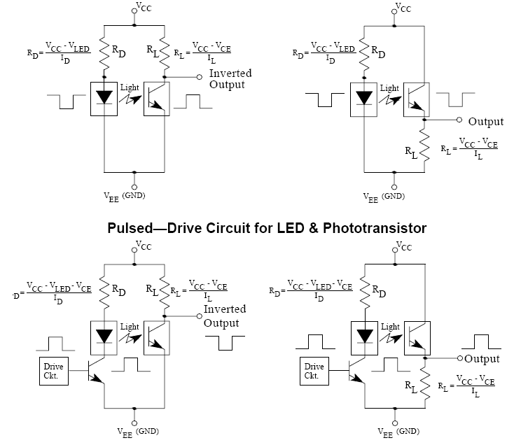
Pulse Driven
RD = (VCC - VLED - VCE) / ID
VCE (Collector-Emitter Saturation Voltage) = 0.4V
VLED 1.8V
VCC 1.9V pulsed output from 3.1V
ID current through resistor 20mA
RD = - 0.3/20m (negative value) so Vcc should be increased so that RD = 0 (no power wastage) => requires additional 0.7V
RL = (VCC - VCE) / IL
RL = (1.9 - 0.4) / 0.25m = 60 Ohm
PRL= 0.252 * 60 = 37.5 mW
LED to pwm supply
period: needle should not pass (generate light signal after how long)
dutycycle: brightness control => sufficient light (voltage calculation)
- mbed pin voltage 3.1V, LED VF = 1.8V => Duty Cycle = VF / Vpin = 0.58064%
- results in Vavg = 1.9V
Phototransistor:
- minimum IC(on) OP550 0.25mA
- saturation voltage Vce OP550 0.4V
- Calculate RC(min) = (VCC - Vsat) / Ic(on)min
- Calculate RC(min) = (VCC - Vsat) / Ic(on)min
Phototransistor
only on when needle pass
generates interrupt signal
emitter = LED, sensor or detector = phototransistor
assembly for good photo-coupling
RC(min) = (1.8 - 0.4) / 0.00025 = 5.6 KOhm
RC(min) = (1.9 - 0.4) / 0.00025 = 6 KOhm
P = I2 * RC = ) = 0.375 mW
Switch Mode
VCC (1.9) < RL * ICC (1.5)
1.9 <
Standard Resistor:
http://www.daycounter.com/Calculators/Standard-Resistor-Value-Calculator.phtml
SCHEMATICS - INFRARED EMITTER DETECTOR:
http://www.societyofrobots.com/schematics_infraredemitdet.shtml

Please log in to post comments.
