Obstacle Avoiding Robot Car Convoy
 Marcus Pereira.
0
replies
Marcus Pereira.
0
replies
Team members
Marcus Pereira, Adam Molander, Edwin Torres

Project Description
The goal of this project is to build a convoy of robot cars with one "leader" robot and one or more "follower" robots. The leader is capable of scanning for and avoiding obstacles in its path. It does so by using the Sharp IR sensors. The leader is also responsible for sending appropriate commands to the follower robots to "blindly" follow the leader's trajectory and avoid obstacles. This project uses Xbee radio modules for communication between the robots and a C# GUI which plots the course of the leader robot.
Components required
Following is a list of important components required besides the mbed-LPC1768 module https://www.sparkfun.com/products/9564 and other miscellaneous items such as resistors, capacitors, jumper wires, solderless breadboards, zip-ties, double-sided sticky tape and AA batteries.
- Leader robot
- 1 x SparkFun RedBot Basic Kit https://www.sparkfun.com/products/13166
- 1 x Wheel encoder kit https://www.sparkfun.com/products/12629
- 3 x Sharp IR distance sensors https://www.sparkfun.com/products/12728
- 3 x JST jumper wires for Sharp IR sensors https://www.sparkfun.com/products/9915
- 1 x Standard RC servo https://www.servocity.com/hs-322hd-servo
- 2 x Sparkfun Xbee Explorer USB https://www.sparkfun.com/products/11812 (1 for the leader robot and 1 for C# GUI )
- 2 x Xbee WiFi module with wire antenna https://www.sparkfun.com/products/12571 (1 for the leader robot and 1 for C# GUI )
- 1 x Dual H-Bridge motor driver breakout https://www.pololu.com/product/713
- 1 x 3.3 V voltage regulator http://www.digikey.com/product-detail/en/LD1117V33/497-1491-5-ND/586012
- Follower robot
- 1 x SparkFun RedBot Basic Kit https://www.sparkfun.com/products/13166
- 1 x Wheel encoder kit https://www.sparkfun.com/products/12629
- 1 x Sparkfun Xbee Explorer USB https://www.sparkfun.com/products/11812 (Add 1 for each additional follower robot)
- 1 x Xbee WiFi module with wire antenna https://www.sparkfun.com/products/12571 (Add 1 for each additional follower robot)
- 1 x Dual H-Bridge motor driver breakout https://www.pololu.com/product/713
- 1 x 3.3 V voltage regulator http://www.digikey.com/product-detail/en/LD1117V33/497-1491-5-ND/586012
The Leader Robot
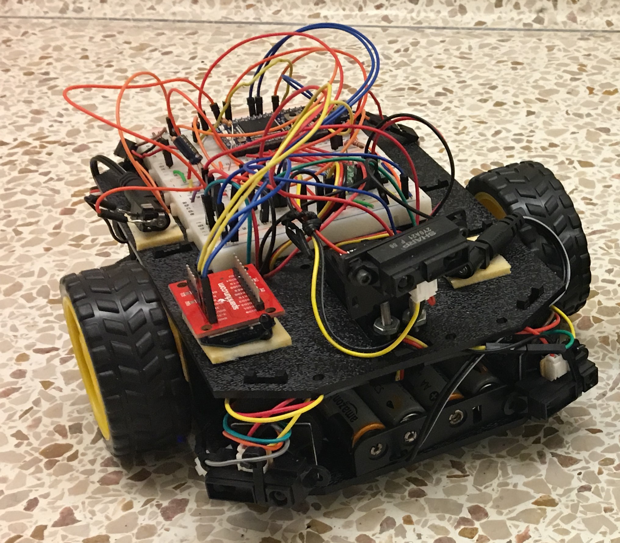
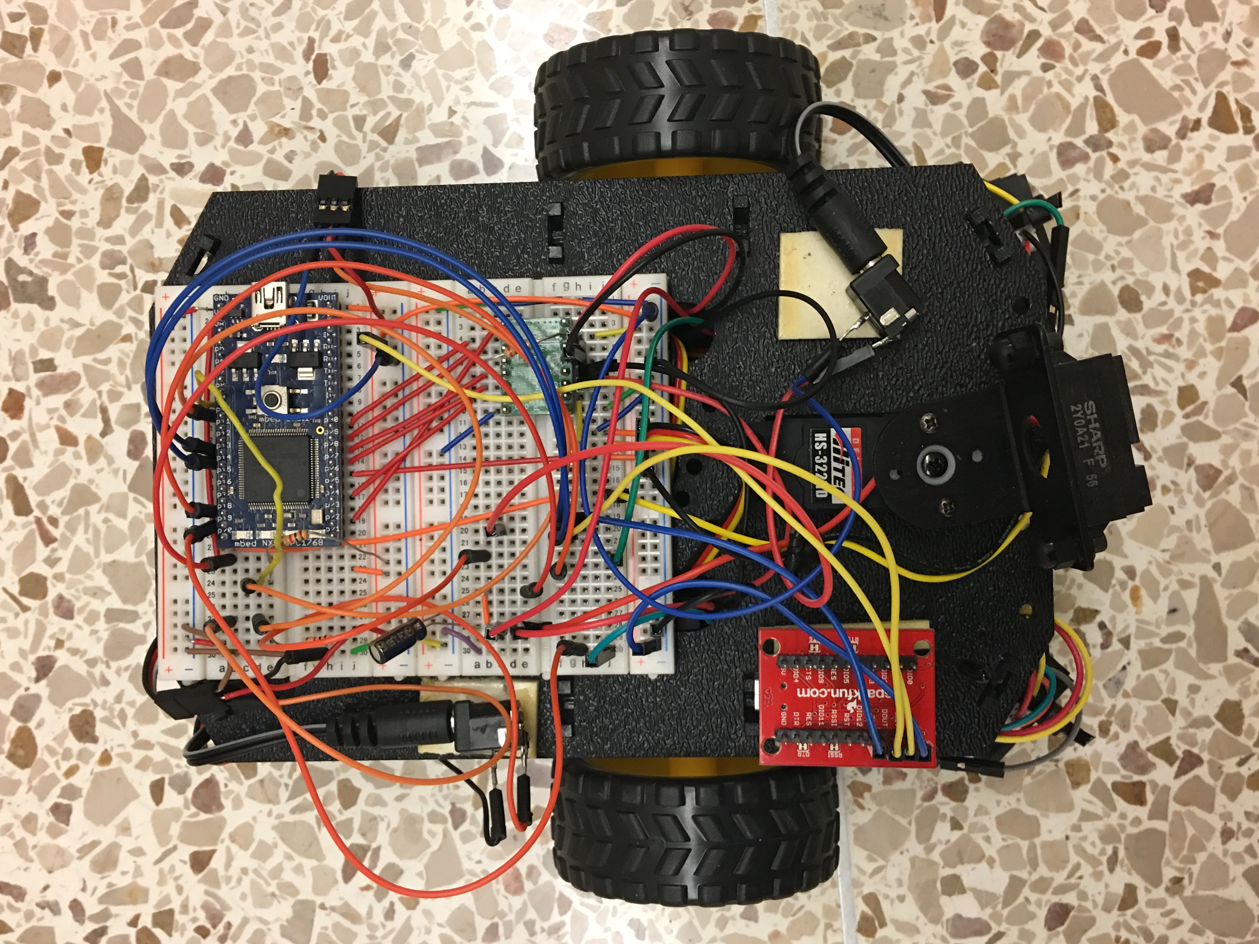
 As seen in the pictures, the Sharp IR sensors are mounted to the front, lower-left and lower-right sides of the leader robot. The front facing IR sensor is mounted on a standard RC servo to allow the leader to "look around" and scan the immediate vicinity for obstacles. The IR sensors on lower left and right sides are used by the leader to see obstacles on the sides where the leader is blind. This helps to ensure that the wheels of the leader do not collide with a side-obstacle after it makes a potential decision to avoid that obstacle and move past it.

When anyone of the 3 IR sensors detects an object in front of it, the mbed commands the car to halt. It then sends a message via the Xbee radio module containing the amount of time to travel, in a straight line path, to the follower robot(s). While the follower robot covers this distance, the leader robot "looks around" using the servo motor to rotate the front-facing IR sensor which allows the sensor to scan a 90 degree cone in front of the robot. The mbed evaluates the direction with least obstruction and commands the robot to turn towards it. This is followed by sending a message to the follower robot(s) and the C# GUI with the angle to turn left or right in order to avoid the object. The leader robot is constantly sending its location to the C# GUI for plotting the convoy trajectory.
A Follower Robot
The follower robots are "blind" to obstacles i.e. they do not have IR sensors for obstacle detection. They are only capable of following a straight line path using PID control and making turns. Hall-effect encoder sensors mounted adjacent to each motor provides speed information for closed loop feedback control. The trajectory of the follower robot is based on commands received from the leader robot through the Xbee radio module connected to the follower's mbed.
The C# GUI
The GUI initially establishes a serial connection with the Xbee module connected to the laptop. It then waits for the user to give an initial angle (or desired orientation shown below by the blue dashed line) for the leader robot to begin moving in. Once the leader robot receives this direction, it makes the turn towards the desired orientation and begins moving in a straight line path in that direction. The C# GUI receives the (x,y) coordinates of the leader's trajectory and plots them on a chart as seen in the picture below.


Schematic Diagram for Leader Robot

Schematic Diagram for Follower Robots

Code for mbed on Leader robot
Code for mbed on Follower robots
Code for C# GUI
Code written in Microsoft Visual Studio 2015
using System;
using System.Collections.Generic;
using System.ComponentModel;
using System.Data;
using System.Drawing;
using System.Linq;
using System.Text;
using System.Threading.Tasks;
using System.Windows.Forms;
using System.IO.Ports;

namespace Xbee
{

    delegate void drawChartCallBack(double X, double Y);
    public partial class Form1 : Form
    {
        private StringBuilder recievedData = new StringBuilder();
        public Form1()
        {
            InitializeComponent();
        }

        private void Form1_Load(object sender, EventArgs e)
        {
            foreach (string portname in SerialPort.GetPortNames())
            {
                comboBox1.Items.Add(portname);
            }
            timer1.Start();

                chart1.Series[0].BorderWidth = 4;
                chart1.ChartAreas[0].AxisX.LineWidth = 0;
                chart1.ChartAreas[0].AxisX.MajorTickMark.Enabled = false;
                chart1.ChartAreas[0].AxisX.LabelStyle.Enabled = false;
                chart1.ChartAreas[0].AxisY.LineWidth = 0;
                chart1.ChartAreas[0].AxisY.MajorTickMark.Enabled = false;
                chart1.ChartAreas[0].AxisY.LabelStyle.Enabled = false;
                chart1.ChartAreas[0].AxisX.Maximum = 10000;
                chart1.ChartAreas[0].AxisY.Maximum = 10000;
                chart1.ChartAreas[0].AxisX.Minimum = -10000;
                chart1.ChartAreas[0].AxisY.Minimum = -10000;
         }

        private void Open_Port_Click(object sender, EventArgs e)
        {
            serialPort1.PortName = comboBox1.Text;
            if (!serialPort1.IsOpen)
             {
               serialPort1.Open();
                serialPort1.BaudRate = 115200;
             }
        }

        private void Close_Port_Click(object sender, EventArgs e)
        {
            if (serialPort1.IsOpen)
            {
                serialPort1.Close();
            }
        }

        private void Send_Click(object sender, EventArgs e)
        {
            if (serialPort1.IsOpen)
            {
               serialPort1.Write(textBox1.Text + "\n\r");
            }
        }

        private void serialPort1_DataReceived(object sender, SerialDataReceivedEventArgs e)
        {
            recievedData.Append(serialPort1.ReadExisting());
            string tempString1;
            string Xbuf;
            string Ybuf;
            tempString1 = serialPort1.ReadLine();
            if (tempString1 == "+")
            {
                Xbuf = serialPort1.ReadLine();
                Ybuf = serialPort1.ReadLine();

                double X;
                double Y;
                if (double.TryParse(Xbuf, out X) && double.TryParse(Ybuf, out Y))
                {
                    drawChart(X, Y);

                }
            }
            serialPort1.DiscardInBuffer();
        }

        private void drawChart(double X, double Y)
        {
            System.Windows.Forms.DataVisualization.Charting.ImageAnnotation logo = new System.Windows.Forms.DataVisualization.Charting.ImageAnnotation();
            logo.AxisX = chart1.ChartAreas[0].AxisX;
            logo.AxisY = chart1.ChartAreas[0].AxisY;

            if (this.chart1.InvokeRequired)
            {
                drawChartCallBack d = new drawChartCallBack(drawChart);
                this.Invoke(d, new object[] { X, Y });
            }
            else
            {
                chart1.Annotations.Clear();
                chart1.Series[0].Points.AddXY(X, Y);
                chart1.Series[0].ChartType = System.Windows.Forms.DataVisualization.Charting.SeriesChartType.Line;

                logo.X = X;
                logo.Y = Y;
                logo.Image = "C:\\Users\\Marcus\\Desktop\\ECE-4180\\smallcar.png";
                chart1.Annotations.Add(logo);

            }
         }

        private void timer1_Tick(object sender, EventArgs e)
        {
            richTextBox1.Text = recievedData.ToString();
        }

        private void trackBar1_Scroll(object sender, EventArgs e)
        {
            textBox2.Text = trackBar1.Value.ToString();
        }

        private void button1_Click(object sender, EventArgs e)
        {
           int desired_orn = trackBar1.Value;
            chart1.Series.Add("Line");
            chart1.Series["Line"].Points.AddXY(0, 0);
            double y_val = Math.Sin(desired_orn*Math.PI/180.0) *10000.0;
            double x_val = Math.Cos(desired_orn * Math.PI / 180.0) * 10000.0;
            chart1.Series["Line"].Points.AddXY(x_val, y_val);
            chart1.Series["Line"].ChartType = System.Windows.Forms.DataVisualization.Charting.SeriesChartType.Line;
            chart1.Series["Line"].LegendText = "Desired Orientation";
            chart1.Series["Line"].BorderDashStyle = System.Windows.Forms.DataVisualization.Charting.ChartDashStyle.Dash;
            chart1.Series["Line"].BorderWidth = 3;
            chart1.Series["Line"].Color = Color.Blue;
           if (serialPort1.IsOpen)
           {
             serialPort1.Write(textBox2.Text + "+");
           }
        }

    }
}
Video Demos
- Below is a video of the leader car avoiding our feet and sending instructions to the follower car. The C# GUI is plotting their path as seen in the laptop screen at the end of video.
- Below is a video of the leader car entering into an unkonwn area with obstacles. It halts everytime it detects an obstacle ahead and looks around in the immediate vicinity for a direction to proceed with minimum obstruction. It then relays all its decisions to the follower robot to safely navigate the unknown terrain. As you will see in the video below, the leader can only find local solutions to avoid obstacles. To a human the obvious solution would be to navigate through the obstacles by turning to the right and exiting this area with obstacles. This would be the global optimal solution for the leader robot's trajectory. This is a feature worth exploring for future development of robot car convoys. Our conclusion of the leader's decision to turn left, in the video you will see below, is heavily based on what the front facing IR sensor "sees as it looks around". This decision can be improved by using a combination of IR and sonar sensors, along with an IMU for robust decision making.
- Below is a video of the leader finding a clear path in between 2 obstacles and commanding the follower to make the right decisions to safely navigate by avoiding the obstacles.
- Another video with GUI plotting
Assembly instructions for Shadow robot chassis
Link to Sparkfun assembly guide
Assembly video tutorial
Please log in to post comments.
Obstacle Avoiding Robot Car Convoy
Project team members; Marcus Pereira, Adam Molander and Edwin Torres
Page owner: Marcus Pereira
Created 11 Dec 2016.
Last updated 12 Dec 2016