ECE 4180 Project: Balloon Popping RC Car
Teammates: Omari Hodge and Marzeah Khorramabadi
Summary: An RC car built from the SparkFun kit car base is controlled wirelessly through two XBee S1 802.15.4 RF modules. An Arduino controls the transmitting XBee which relays the data from user controlled joysticks and broadcasts the byte stream to the receiver. The receiving XBee is connected to the mBed and there useful data is retrieved from the byte stream and used to control the car's DC motors and servos on the robot arm. The RC car is user controlled and can go forwards, reverse, and turn in either direction. The robot arm attached to the car can swivel and bend to position itself to pop a balloon.
Parts List
- (2) XBee S1 802.15.4 RF Modules
- SparkFun Motor Driver - Dual TB6612FNG
- 2 Joysticks
- (2) DAGU Hobby Gear Motors - 140 RPM , 4.5 V
- SparkFun XBee Explorer Dongle
- 3 Servo Robotic Arm
- 5V External Power Supply
- Arduino
- mBed
Wiring
| H-Bridge | Mbed |
|---|---|
| VM | 5V Power Supply |
| VCC | 3.3V |
| PWMA | p21 |
| PWMB | p22 |
| AIN1 | p10 |
| AIN2 | p9 |
| BIN1 | p11 |
| BIN2 | p12 |
| STBY | pull up (VCC) |
| H-Bridge | Motor A |
|---|---|
| A01 | red lead |
| A02 | black lead |
| H-Bridge | Motor B |
|---|---|
| B01 | red lead |
| B02 | black lead |
| Receiver Xbee | Mbed |
|---|---|
| RST | p7 |
| DOUT | p14 (Serial RX) |
| VCC | 3.3V |
| GND | GND |
| Transmitter Xbee | Arduino |
|---|---|
| DIN | p1 (TX) |
| VCC | 3.3V |
| GND | GND |
| Analog 1 | Arduino |
|---|---|
| VCC | 5V |
| VERT | A0 |
| HORZ | A1 |
| SEL | p3 |
| GND | GND |
| Analog 2 | Arduino |
|---|---|
| VCC | 5V |
| VERT | A2 |
| HORZ | A3 |
| SEL | p2 |
| GND | GND |
Photos
Information
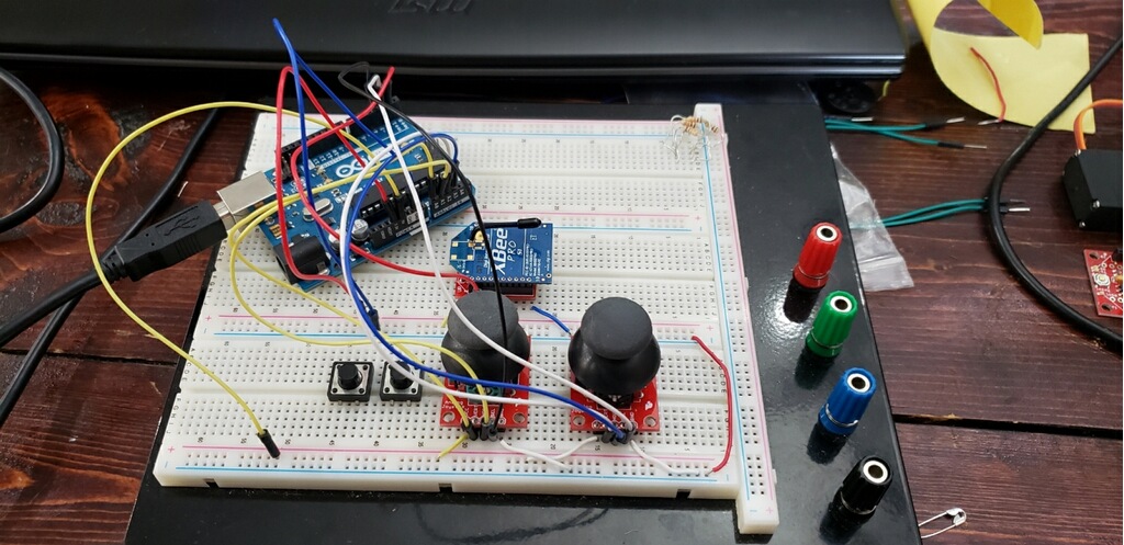
The wireless controller was built on a bread board with an Arduino taking in the input from two joysticks and writing the output to the XBee transmitter. Photo of the controller is shown below.

Information
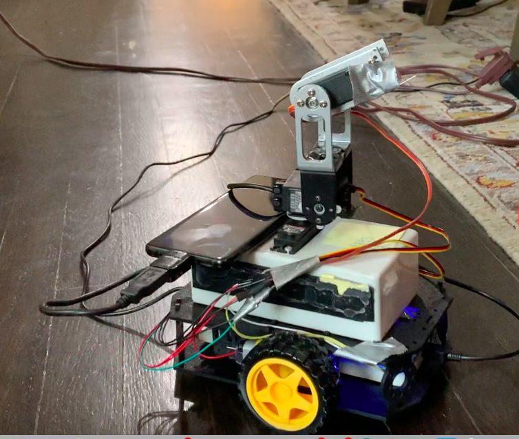
The RC car was built off the base from the ECE 4180 kit and a preassembled robotic arm was attached to the base. Photo of the RC car is shown below.

Information
A Mbed was on board the RC car and communicates with the receiving XBee to output data to the DC motors and robotic arm servos. Photo of the board wiring within the RC car is shown below.

Code
Import program4180_Crane_Robot
Code Controlling Robot DC Motors and Crane Servos
main.cpp
/*   ~ Xbee Transmitter for Crane Robot ~

  Ardunio reads analog readinds of joysticks and Xbee transmits a serial line for the reciver xbee to decode.

  Omari Hodge                  */

int vertCar = A0; // forward and backward motions of car
int horzCar = A1; //turning motions of car
int vertCrane = A2; //up and down of crane
int horzCrane = A3; //rotation of crane
int wrist1 = 2;
int wrist2 = 3;


//Variable holders for the potentiometers:
int horzCarr ; //Value from pot
int vertCarr ; //Value from pot
int horzCraner ; //Value from pot
int vertCraner ; //Value from pot
int wrist1r ;
int wrist2r ;

void setup() {
  pinMode(wrist1,INPUT_PULLUP);
  pinMode(wrist2,INPUT_PULLUP);
  //Start the serial communication
  Serial.begin(9600); //Baud rate must be the same as is on xBee module

}

void loop() {

    //Read the analog value from pot and store it to respective variables
    horzCarr = analogRead(horzCar);
    vertCarr = analogRead(vertCar);
    horzCraner = analogRead(horzCrane);
    vertCraner = analogRead(vertCrane);

    if (digitalRead(wrist1) == HIGH)
      wrist1r = 35;
    else
      wrist1r = 36;

    if (digitalRead(wrist2) == HIGH)
      wrist2r = 35;
    else
      wrist2r = 36;

    //Map the analog value to char range
    horzCarr = map (horzCarr, 0, 1023, 33, 126);
    vertCarr = map (vertCarr, 0, 1023, 33, 126);
    horzCraner = map (horzCraner, 0, 1023, 33, 126);
    vertCraner = map (vertCraner, 0, 1023, 33, 126);

  //Send the message:
  Serial.write('<');  //Starting symbol
  Serial.write('a');
  Serial.write(horzCarr);
  Serial.write(' ');
  Serial.write('b');
  Serial.write(vertCarr);
  Serial.write(' ');
  Serial.write('c');
  Serial.write(horzCraner);
  Serial.write(' ');
  Serial.write('d');
  Serial.write(vertCraner);
  Serial.write(' ');
  Serial.write('e');
  Serial.write(wrist1r);
  Serial.write(' ');
  Serial.write('f');
  Serial.write(wrist2r);
  Serial.println('>');//Ending symbol


}
Information
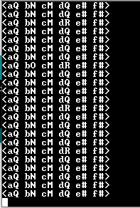
The XBee connected to the Arduino outputs the following serial lines shown below to the Mbed. The code on the Mbed breaks apart the serial input into useful data for controlling the motors and servos. Each lower case letter represents the start of data values from the joysticks and each other character is a ascii value between 33 and 126.

Demo Video
Presentation
Information
To view the presentation without audio in google slides visit link: https://docs.google.com/presentation/d/1iXtysHugeAc1c7f9uZae5DX9Oba-Up0UncEV6mvbTV0/edit?usp=sharing
References
Simple XBee tutorial, How to set channels: https://spin.atomicobject.com/2016/07/18/xbee-tutorial/
Using XBee with Arduino/set up: https://www.instructables.com/id/How-to-Use-XBee-Modules-As-Transmitter-Receiver-Ar/
Joystick and XBee Controls for Hovercraft: http://blog.ilektronx.com/2011/08/xbee-enabled-joystick-piii.html
Please log in to post comments.

