Arduino board run on Mbed-os6.8.1 (only test purpose not official). Need Mbed Studio(1.3.1) not online compiler. If you compile on the online compiler, you can get a hex file but it does NOT work!!!
Dependencies: APDS_9960 LPS22HB LSM9DS1 HTS221
1) DAPLink(LPC11U35)の準備
使用したボード →https://akizukidenshi.com/catalog/g/gK-12144/
プログラムは、nRF52840-MDK用に公開されているDAPLinkのコンパイル済のバイナリコードを使わせていただきました。
https://github.com/makerdiary/nrf52840-mdk/tree/master/firmware/daplink
LPC11U35への書込みは、SW1(ISP)を押したままSW2(RESET)を操作するとPCに「CRP DISABLD」という名称でマウントされるので、書込まれているfirmware.binを削除してから、上記のbinファイルをコピーすれば書き込みが行われます。
書込み完了後にSW1を押さずに起動すれば、「DAPLINK」として認識されます。
DETAILS.TXTでDAPLinkの内容を確認できます。
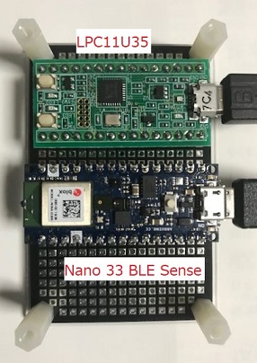
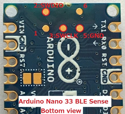
2) 接続
| Arduino Nano 33 BLE Sense | LPC11U35 Interface CPU | コメント |
| J3:Pin2 (ボード裏のパッド) | CN1:Pin3 P0_7 | SWDIO |
| J3:Pin3 (ボード裏のパッド) | CN1:Pin4 P0_8 | SWCLK |
| JP2:Pin14 GND | CN2:Pin1 GND | GND |
3)USBSerial
シリアル出力は、NANO 33 BLE SENSEボードのUSB端子経由で出力されます。
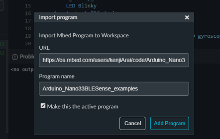
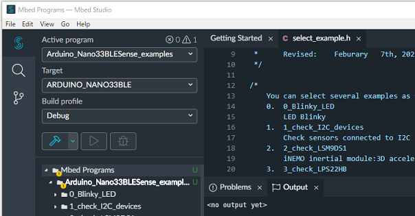
4)Mbed Studio 1.3.1を使って開発のこと!(オンラインコンパイラでは動作しません!)
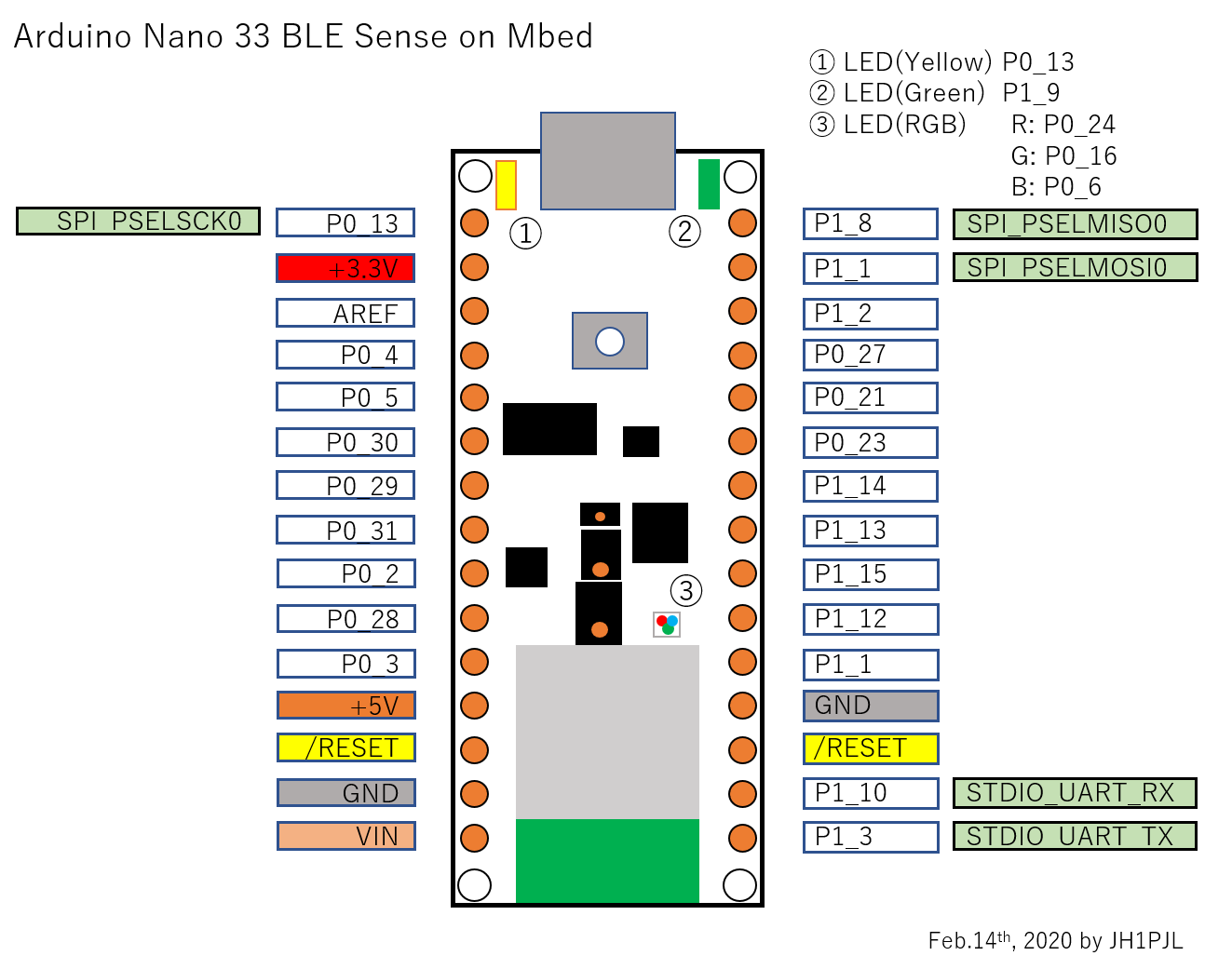
5)ボードピン配置
Diff: nano33blesense_iodef.h
- Revision:
- 1:cce280da16d4
- Parent:
- 0:f1a10797d9f6
- Child:
- 2:9ee17e6e5900
--- a/nano33blesense_iodef.h	Fri Feb 07 01:21:16 2020 +0000
+++ /dev/null	Thu Jan 01 00:00:00 1970 +0000
@@ -1,97 +0,0 @@
-/*
- * Nano 33 BLE Sense
- *      Arudiono nRF52840 module
- *
- * Copyright (c) 2020 Kenji Arai / JH1PJL
- *      http://www7b.biglobe.ne.jp/~kenjia/
- *      https://os.mbed.com/users/kenjiArai/
- *      Started:    January   22nd, 2020
- *      Revised:    Feburary   5th, 2020
- *
- */
-
-// LEDs
-#define PIN_YELLOW      P0_13
-#define PIN_GREEN       P1_9
-#define PIN_LR          P0_24
-#define PIN_LG          P0_16
-#define PIN_LB          P0_6
-
-// APDS-9960
-#define PIN_APDS_INT    P0_19
-
-// SPI
-#define PIN_SPI_MOSI    P1_1
-#define PIN_SPI_MISO    P1_8
-#define PIN_SPI_SCK     P0_13
-
-// External I2C
-#define PIN_EXT_SDA     P0_31
-#define PIN_EXT_SCL     P0_2
-
-// Internal I2C
-#define PIN_SDA1        P0_14
-#define PIN_SCL1        P0_15
-
-// Power line control
-#define PIN_I2C_PULLUP  P1_0
-#define PIN_VDD_ENV     P0_22
-#define PIN_APDS_PWR    P0_20
-#define PIN_MIC_PWR     P0_17
-
-//-------- Reference --------------------------------------------------
-#if 0
-https://github.com/arduino/ArduinoCore-nRF528x-mbedos
-\variants\ARDUINO_NANO33BLE\variant.cpp
-&
-\variants\ARDUINO_NANO33BLE\pins_arduino.h
-
-  // D0 - D7
-  P1_3,     0
-  P1_10,    1
-  P1_11,    2
-  P1_12,    3
-  P1_15,    4
-  P1_13,    5
-  P1_14,    6
-  P0_23,    7
-
-  // D8 - D13
-  P0_21,    8
-  P0_27,    9
-  P1_2,     10  PIN_SPI_SS    (10u)
-  P1_1,     11  PIN_SPI_MOSI  (11u)
-  P1_8,     12  PIN_SPI_MISO  (12u)
-  P0_13,    13  LED_BUILTIN (13u) / PIN_SPI_SCK   (13u)
-
-  // A0 - A7
-  P0_4,     14  PIN_A0 (14u)
-  P0_5,     15  PIN_A1 (15u)
-  P0_30,    16  PIN_A2 (16u)
-  P0_29,    17  PIN_A3 (17u)
-  P0_31,    18  PIN_A4 (18u) / PIN_WIRE_SDA        (18u)
-  P0_2,     19  PIN_A5 (19u) / PIN_WIRE_SCL        (19u)
-  P0_28,    20  PIN_A6 (20u)
-  P0_3,     21  PIN_A7 (21u)
-
-  // LEDs
-  P0_24,    22  LEDR        (22u)
-  P0_16,    23  LEDG        (23u)
-  P0_6,     24  LEDB        (24u)
-  P1_9,     25  LED_PWR     (25u)
-
-  P0_19,    26  PIN_INT_APDS (26u)
-
-  // PDM
-  P0_17,    27  PIN_PDM_PWR  (27)
-  P0_26,    28  PIN_PDM_CLK  (28)
-  P0_25,    29  PIN_PDM_DIN  (29)
-
-  // Internal I2C
-  P0_14,    30  PIN_WIRE_SDA1       (30u)
-  P0_15,    31  PIN_WIRE_SCL1       (31u)
-
-  // Internal I2C
-  P1_0,     32  PIN_ENABLE_SENSORS_3V3     (32u)
-  P0_22,    33  PIN_ENABLE_I2C_PULLUP      (33u)
-#endif