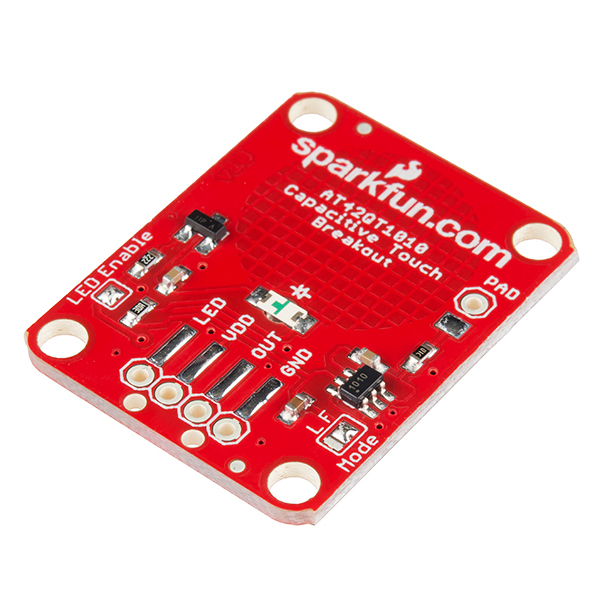
AT42QT1010 Capacitive Touch Sensor

The AT42QT1010 Capacitive Touch Breakout (https://www.sparkfun.com/products/12041) is a single output touch sensor. The image above shows the back of the board.
When a fleshy object (such as a finger) comes within proximity of the capacitive pad on the board, the device will drive OUT high as a digital signal. Its function is simple in its original state, so only the VDD, GND, and OUT signals are used for operation.
| mbed Pin | Sensor Pin |
|---|---|
| P26 | LED |
| VOUT=3.3V | VDD |
| P25 | OUT |
| GND | GND |
Some changes can be made to enhance the functionality of the sensor, but require modifications to the circuitry on the breakout board:
- There is an on-board LED that comes connected to the OUT of the device, going high when the sensor output does. It can be controlled independently through the LED sensor pin if the the LED Enable jumper is manually de-soldered.
- The breakout can switch between two operation modes. By default it is in Fast Mode, denoted by the connection between the center pad and the F in the mode area. This mode operates with only a 1ms delay between data bursts, put consumes 200-750 micro Amps. There is also a Low Power Mode that operates on only 15-75 micro Amps, but is less responsive by having an 80ms sleep response after data bursts. To switch to this mode, the F area connection must be de-soldered, and the L area connected to the center pad.
- External pads can also be used to extend the sensor. Any electrode can be wired to the PAD area of the breakout board to act as an input to the IC. This includes any kind of dielectric material, noting that a larger and thinner pad will be more sensitive to touch. Be weary of making the electrode too sensitive, as this may have a negative effect on performance.
It should also be mentioned that the output signal from the breakout board can only be held high for a short period of time depending on the mode (can range from about 6-60 seconds). After this point, the chip re-calibrates itself based on the input. Removing the input and waiting for a moment will return operation to normal. To manually re-calibrate the device must be powered down, where upon restarting it will adjust to its surroundings.
Note
Keep objects away from the electrode pad during start-up to maximize responsiveness of the sensor. This process takes about 100 ms.
Import library
Public Member Functions |
|
| AT42QT1010 (PinName) | |
|
Define the device without use of the on-board LED.
|
|
| AT42QT1010 (PinName, PinName) | |
|
Define the device using both breakout I/O pins.
|
|
| void | write (int state) |
|
Writes to the LED, if defined.
|
|
| int | read () |
|
Take in the current value being output by the device.
|
|
| operator int () | |
|
Shorthand for
read()
.
|
|
| void | attach_rise (void(*fpr)(void)) |
|
Initiate interrupts for the rising edge of data.
|
|
| void | attach_fall (void(*fpr)(void)) |
|
Initiate interrupts for the falling edge of data.
|
|

In the example below, two of the mbed LEDs are used to show the status of the sensor, and two display an interrupt-driven counter that increments on the rising edge (each time input comes into contact with the sensor). In addition, the on-board led is written to also display the opposite of the output. Note that this assumes the LED enable has been de-soldered on the board.
An important note about the interrupt is that it requires a falling and rising edge indicator, as well as variables to show its status. This is because the output of the sensor when high is actually a series of data bursts (refer to sensor modes for timing). The example program shows a way to process data on "true" edges. This does not eliminate the problem of the data bursts entirely, but does function for readings of a few seconds. Longer times between the _new_sig value read decrease the chance of of false interrupts, but decrease the productivity of the main function.
main.cpp
#include "mbed.h"
#include "AT42QT1010.h"

DigitalOut read_led(LED1);
DigitalOut auto_led(LED2);
DigitalOut i_led1(LED3);
DigitalOut i_led2(LED4);
AT42QT1010 touch_sensor(p23,p21);

//Global variables to control interrupt timing
int _old_sig=0;
int _new_sig=0;

void rise_interrupt(){
    static int count=0;
    //Only execute on true rise
    if(_old_sig==0 && _new_sig==1){
        _old_sig=1;
        //Use LED3 and LED4 to display count
        count++;
        i_led2=(count)%2;
        i_led1=(count>>1)%2;
    }
}
void fall_interrupt(){
    //Trigger indication of true fall
    if(_new_sig==0) _old_sig=0;
}

int main() {
    //Set up the rising and falling edge interrupts
    touch_sensor.attach_rise(&rise_interrupt);
    touch_sensor.attach_fall(&fall_interrupt);
    while(1) {
        //Declare the current status of the sensor,
        //and give a window of time to process.
        _new_sig = touch_sensor;
        wait(.1);
        //Member function demonstration
        read_led = touch_sensor.read();
        auto_led = touch_sensor;
        touch_sensor.write(!auto_led);
    }
}
Import programAT42QT1010_Hello_world
Example Hello World example for interfacing the AT42QT1010 Device
Below is a video of the Hello World program being run. In the latter part, the sensor is held down to demonstrate the recalibration feature. Note how prolonged input displays the data burst problem from earlier, incrementing the counter even though the sensor is still held high.
Please log in to post comments.
