Awkward Segway: A Self-Balancing Bot

Overview
Team Members: Anthony Agnone, Jay Danner, Nico van Duijn, Samer Mabrouk.
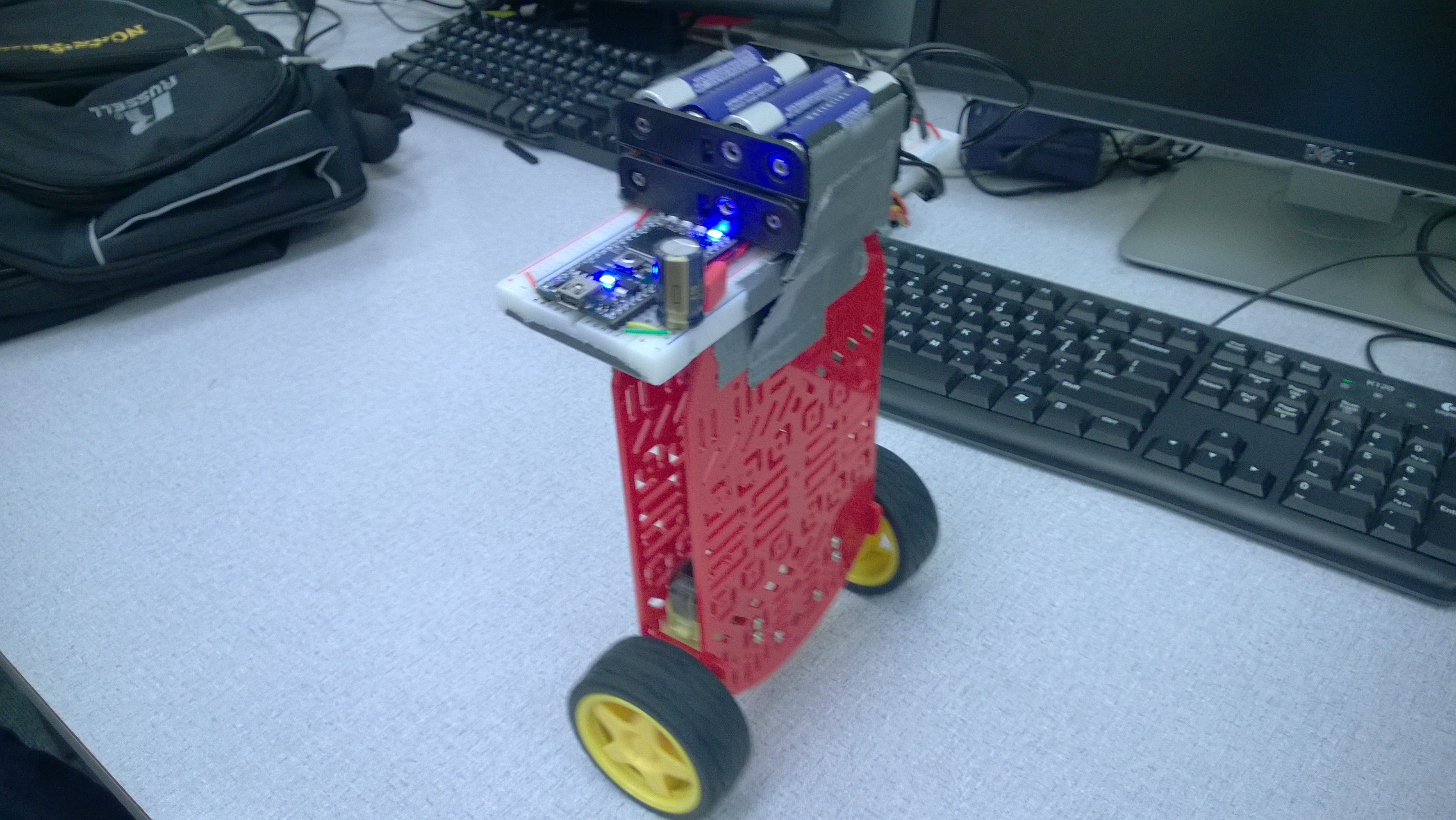
This project consists of a robot balancing vertically on two wheels.

We use the 9-axis IMU LSM9DS0 to give us Accelerometer and Gyroscope data about the current angle and angular velocity of the robot. This data is then filtered using complementary filters and PID control to drive the two motors. The motors are controlled through digital outputs in their direction and their speed by PWM using an H-bridge.

A user can view relevant control data and send inputs to the Mbed balance controller through a C# GUI. The host PC sends these inputs using a pair of XBee wireless modules, controller via serial connection.
Windows C# Control Panel

Provided with the project is a portable executable that communicates with the Bot via a USB XBee module. The executable opens an available COM port on the host computer and begins communications with the embedded XBee module on the Bot.


The C# GUI allows a user to monitor the following values, under the heading "Mbed Data Values:"
- Accelerometer Bias
- Gyroscope Bias
- Offset Angle
- Current Angular Velocity
- Turnspeed
- PID Terms
The user can also tweak control system values dynamically, under the header "Mbed Programmable Values:"
- KP: "Proportional" term in PID control.
- KI: "Integral" term in PID control.
- KD: "Derviative" term in PID control.
- Global Scalar: Scalar for all output gains.
- Turnspeed: Varies the motor speeds to turn the Bot.
- Desired Angle: Changes the Bot to move forward or backward.
Hardware Used
- Micro-controller: Mbed NXP LPC1768 http://developer.mbed.org/platforms/mbed-LPC1768/
- IMU: LSM9DS0 https://www.sparkfun.com/products/12636
- H-Bridge: Polulu MD08A https://www.pololu.com/product/713
- Spark Fun RedBot Kit: https://www.sparkfun.com/products/retired/12032
Software Used
- LSM9DS0 Library: http://developer.mbed.org/cookbook/LMS9DS0-IMU
- Mbed API
- C#
Assembly

IMU
| IMU Pin | mbed Pin |
|---|---|
| SCL | p10 |
| SDA | p9 |
| Vdd | Vout |
| GND | Gnd |
H Bridge/Mbed
| H Bridge Pin | mbed Pin |
|---|---|
| GND | Gnd |
| VCC | VO |
| VMOT | Vsupply |
| GND | Gnd |
| PWMA | p21 |
| AIN2 | p23 |
| AIN1 | p24 |
| STBY | Vout |
| BIN1 | p26 |
| BIN2 | p25 |
| PWMB | p22 |
| GND | Gnd |
H Bridge/Motors
Left Motor is to the left of the IMU chip, and theRight Motor is to the IMU's right.
| H Bridge Pin | Motor Wires |
|---|---|
| BO1 | Left Motor Black |
| BO2 | Left Motor Red |
| AO2 | Right Motor Black |
| AO1 | Left Motor Red |
XBee
| TX | p13 |
| RX | p14 |
| Vdd | Vout |
| GND | Gnd |
Robot Construction
In order to have a robot with the correct structure, the wheel mounts in the middle of the RedBot kit were moved to the far end of the robot.
After the wheels and DC motors were remounted on one end of the robot, the IMU was placed inline with the wheel axes. The placement of the IMU is important to receiving only rotational data, rather than translational.


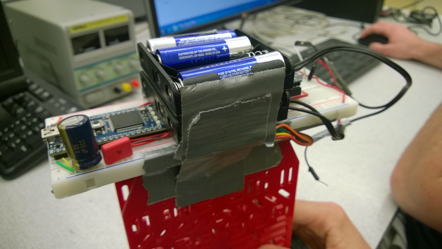
The breadboard connecting the Mbed and the sensors was fastened atop the RedBot. Two 6V battery cradles (8 batteries total) were used to power the Mbed and motors. The cradles, also mounted on the top of the robot, created a top-heavy Bot.

Code
The Bot Mbed-side code is found at the repository below.
Import programAwkwardSegway
Robot that balances on two wheels
Host-side C# Control Panel source code and portable executable is found below.
/media/uploads/jdanner3/controlsystemcommviaxbeesamer.zip
/media/uploads/jdanner3/controlsystemcommviaxbee.exe
Demonstration
The Awkward Segway standing, configured with a Desired Angle of 0.0.
The Awkward Segway turning, configured by varying the Turn Speed dynamically, through the C# Control Panel.
1 comment on Awkward Segway: A Self-Balancing Bot:
Please log in to post comments.


Not bad for a $15 robot base and motor kit, and a $20 IMU chip.