Self Balancing Robot Segway
Team members: Felipe Gramacho, Luke Rucker, Mukund Pandiri, Steven Pyon.
Overview
The idea for this project is to create and assemble a robot that can maintain its balance while moving. There are many challenges that come with this proposition, such as having a physical robot that can stand, while having the necessary components attached to it, as well as finding the right components for development.
To build the robot, we used a chassis kit that came with two DC motors and two wheels. With the wheels and motors attached to the chassis, we attached a breadboard to carry the remaining components.
The main component on the breadboard is an Mbed controller which acts as a control system for the entire device. Connected to the Mbed are an H-bridge, which can drive each of the motors forward and backward, an IMU, which includes a Gyroscope and an Accelerometer which were used to measure its motion and balance, and to provide feedback to the controls, and a bluetooth module for user input of speed (based on desired angle) and constants of the control system.
The following sections outline exactly how this robot was assembled, linking to each of the components used, provide the code written for the control system, and present the final product in pictures, as well as a demonstration video.
Hardware Used
- Mbed NXP LPC1768
- IMU Sensor
- H-Bridge
- Adafruit Bluetooth
- Spark Fun Magician Chassis and Wheels
- DC Motors
- 4 AA Battery and Battery Pack with Barrel Jack
- Barrel Jack Adapter
Software Used
- LMS9DS0-IMU Library
- Mbed API
- Motor Library
- Mbed RTOS
- Bluefruit Connect Application
Robot Assembly
Component Schematic
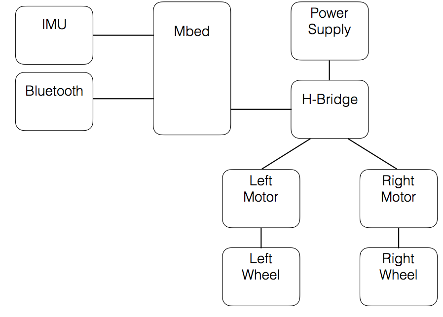
The IMU is used to provide the Mbed with data of the angle using the Gyroscope. This data is then used to drive the H-Bridge which in turn controls two DC Motors directly connected to two wheels. The Bluetooth module is used to input user data to control the robot.
Construction
The two wheels were mounted on the far end of the chassis to create a vertical structure that will require balancing controls. The breadboard connecting the Mbed and the other components was then attached to it as to not create a weight imbalance.
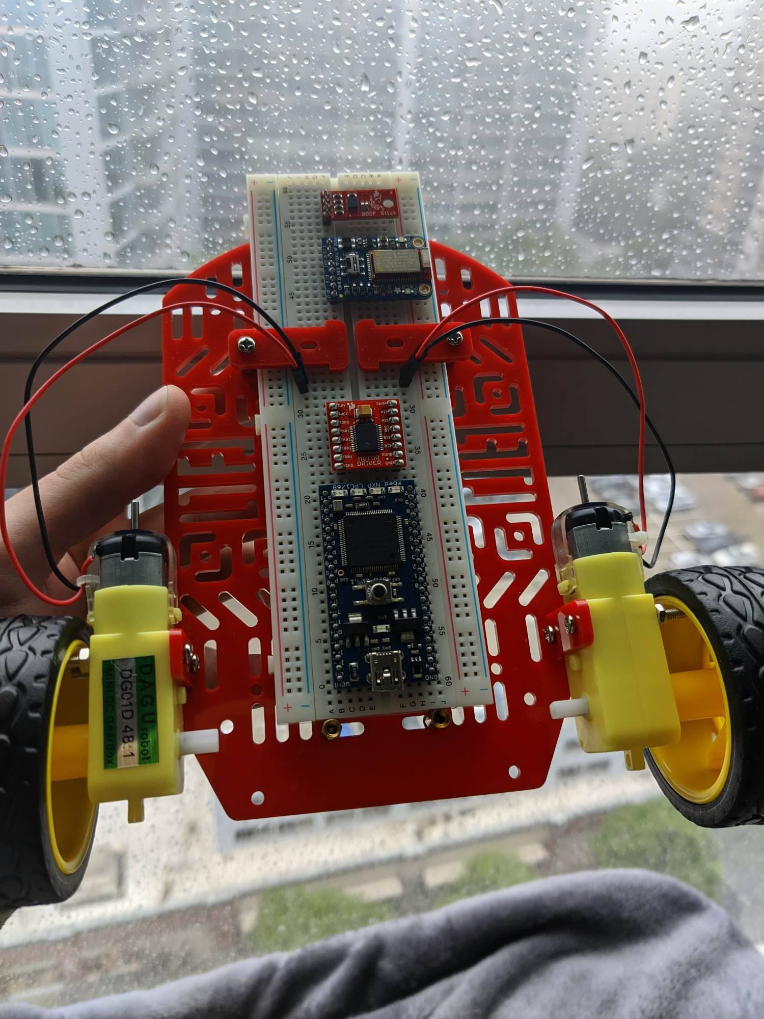
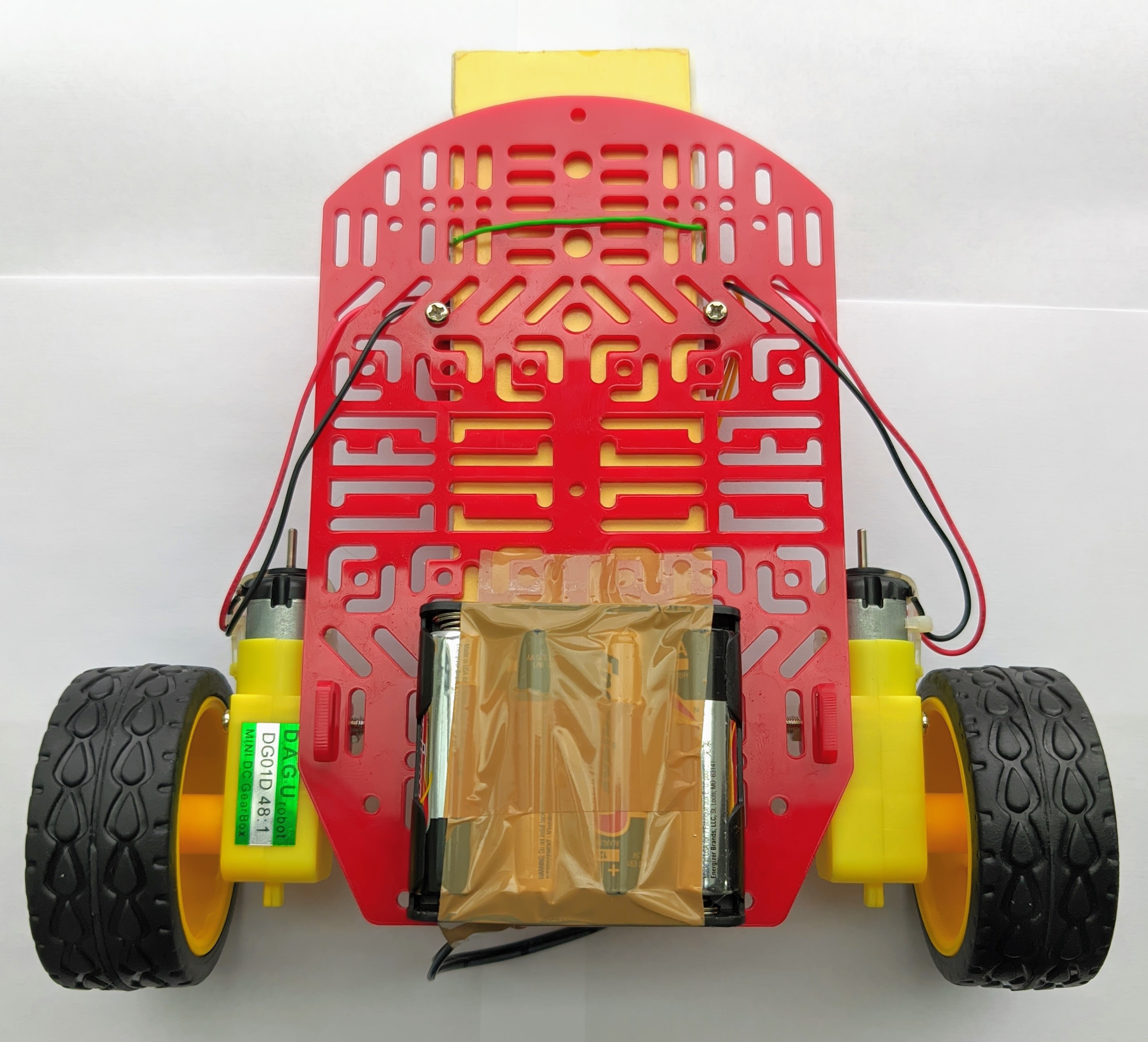
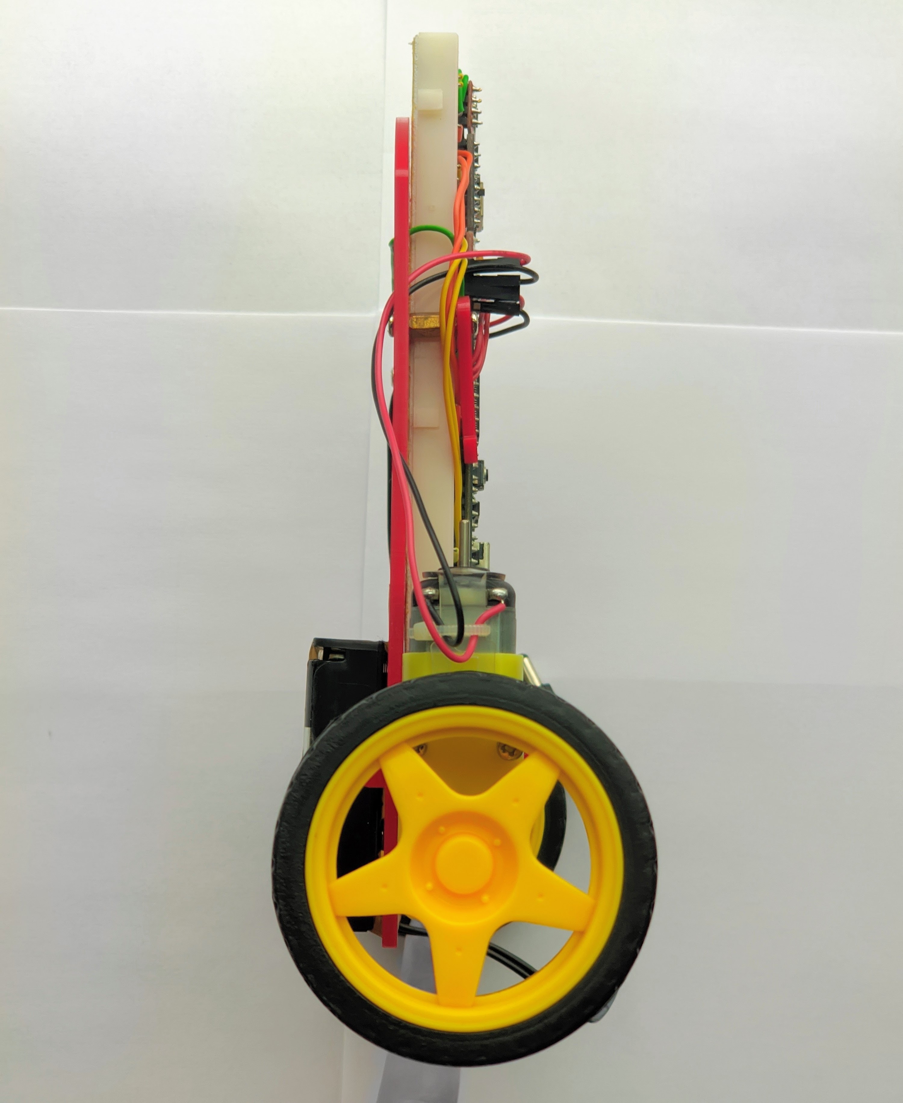
The following is a video showcasing the individual parts of the robot:
The IMU, the H-Bridge, and the bluetooth module were connected to the Mbed and the motors with the following pin configurations:
IMU
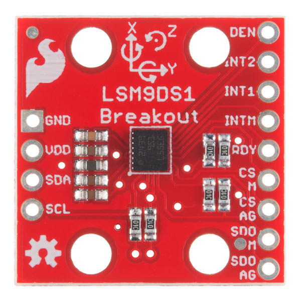
| IMU Pin | Mbed Pin |
|---|---|
| SCL | p10 |
| SDA | p9 |
| VDD | Vout |
| GND | Gnd |
H-Bridge and Motors
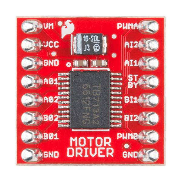
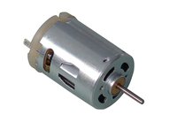
| H-Bridge Pin | Mbed Pin | Motor Wires |
|---|---|---|
| VM | Vsupply | - |
| VCC | VO | - |
| GND | Gnd | - |
| A01 | - | Right Motor Red |
| A02 | - | Right Motor Black |
| B02 | - | Left Motor Red |
| B01 | - | Left Motor Black |
| GND | Gnd | - |
| PWMA | p21 | - |
| AI2 | p23 | - |
| AI1 | p24 | - |
| STBY | Vout | - |
| BI1 | p26 | - |
| BI2 | p25 | - |
| PWMB | p22 | - |
| GND | Gnd | - |
Adafruit Bluetooth
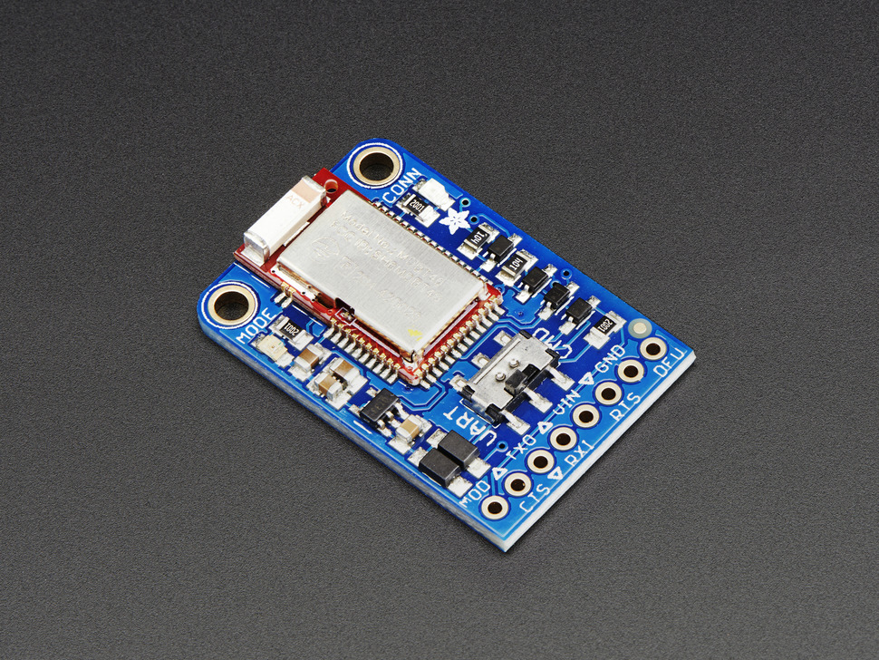
| Adafruit BLE Pin | Mbed Pin |
|---|---|
| Gnd | Gnd |
| Vin | VU |
| RTS | - |
| CTS | Gnd |
| TXO | p27 |
| RXI | p28 |
Power Wiring
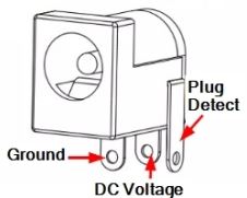
| Barrel Jack Pins | Power Lines |
|---|---|
| Ground | Gnd |
| Power | Vsupply |
| Plug Detect | - |
| Power Lines | Mbed Pin |
|---|---|
| Gnd | Gnd |
| Vsupply | Vin |
Code
The algorithm will make use of a negative feedback loop with an error measured. This error will be represented by the angle by which the device is tilting, as measured by the IMU, and it will be used to adjust the speed of the robot.
The speed will be adjusted according to the principles of controls systems:
- Kp - constant of proportionality
- Ki - constant of integration
- Kd - constant of derivation
- Desired Angle - Angle the robot should be at which can be changed over bluetooth to allow for remote control
Remote Control: The remote control actions can be found in the bluetooth section of the code. Currently the press of the right or left causes the bot to turn but this can be changed by changing the lines that are commented out. We used the Bluefruit connect app (control pad on it) to control the robot.
The code can be found in the following repository:
Import programsegway-balancing
self-balancing-robot
Demonstration
Presentation
Please log in to post comments.
