LPC812 MAX Experiment: Digital In
Experiment: Digital Inputs
In this experiment you will learn how to control the I/O pins of the LPC8xx microcontroller as inputs. More specifically you will learn how to read a digital input that reflects the state of a push-button.
1) Hardware
Information
There is a push-button on the LPC812 MAX Board, but it is only accessible via the I2C-bus and we will get back to that in a later experiment.
In this lab you will need:
- 1x breadboard
- 1x push-button
- 1x 330 ohm resistor
- cables
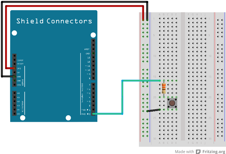
Mount the components on the breadboard and connect the breadboard to the LPC812 as show in the image below.

The +3V3 line is connected to the breadboard even if it is not used in this case. This is because connecting the GND and +3V3 signals to the breadboard is common to start with. The signal will be used in the next lab.
Information
It is common that microcontroller input pins have built-in pull-up resistors. If the input is not driven the input is high. Sometimes the behavior of the pins is very programmable, for example if pull-up or pull-down resistors and input hysteresis shall be enabled. In this experiment a pull-up resistor must be enabled on the input pin. When pressing the push-button it will actively pull the input pin to ground. Otherwise the internal pull-up resistor will pull the input high.
It is important to check the datasheet how strong the pull-up resistors are so that the external signal can pull the pin low and vice versa that the built-in pull-up resistor can pull an inactive signal high.
The series resistor is for protection if the (supposedly) input pin is an output. If that output is pulled high by the microcontroller and the push-button is pressed, the output could be damaged due to excessive current flowing to ground if a series resistor does not limit the current. The situation is not an imaginary situation. Suppose there already is an application running on the microcontroller from a previous experiment. That application might very well use the pin as an output. Before the correct application has been downloaded the damaged can happen. Therefore it is a good practice to add series resistors to all signals that can drive a microcontroller pin - the key in this case, which can drive the signal low.
The pin(s) are specified in the mbed library with the actual pin names as well as some useful aliases:
| Schematic Name | mbed Pin Name | Arduino Shield Alias |
|---|---|---|
| PIO0_0 | P0_0 | D0 |
1) Description
We will start with reading the state of push-button and use the RGB LED to show when the push-button is pressed. The mbed library has a DigitalIn class to simplify using the GPIOs:
The example below shows how to use the Arduino pin alias to create an instance of DigitalIn. The LED class from Lab1 can be used instead, but have been left out here to keep the dependencies down.
main.cpp
#include "mbed.h"

DigitalOut myled(LED_RED);
DigitalIn  button(D0);

int main()
{
    myled = 1;  // Turn LED off

    button.mode(PullUp); // Enable button

    // Enter forever loop
    while(1) {
        // Check if push-button is pressed (input is low)
        if (button.read() == 0) {
            myled = 0; // Button pressed so turn on LED
        } else {
            myled = 1; // Button not pressed so turn off LED
        }
    }
}
Note that the DigitalIn class overrides the integer conversion operator so it is possible to use the button instance directly without calling the read() function like this:
main.cpp
#include "mbed.h"

DigitalOut myled(LED_RED);
DigitalIn  button(D0);

int main()
{
    myled = 1;  // Turn LED off

    button.mode(PullUp); // Enable button

    // Enter forever loop
    while(1) {
        // Check if push-button is pressed (input is low)
        if (!button) {
            myled = 0; // Button pressed so turn on LED
        } else {
            myled = 1; // Button not pressed so turn off LED
        }
    }
}
Download one of the examples above and test your breadboard setup.
2) Hardware
In this lab you will need:
- 1x breadboard
- 2x push-buttons
- 2x 330 ohm resistor
- 1x 1.5 kohm resistor
- 1x buzzer
- 1x PNP transistor
- cables
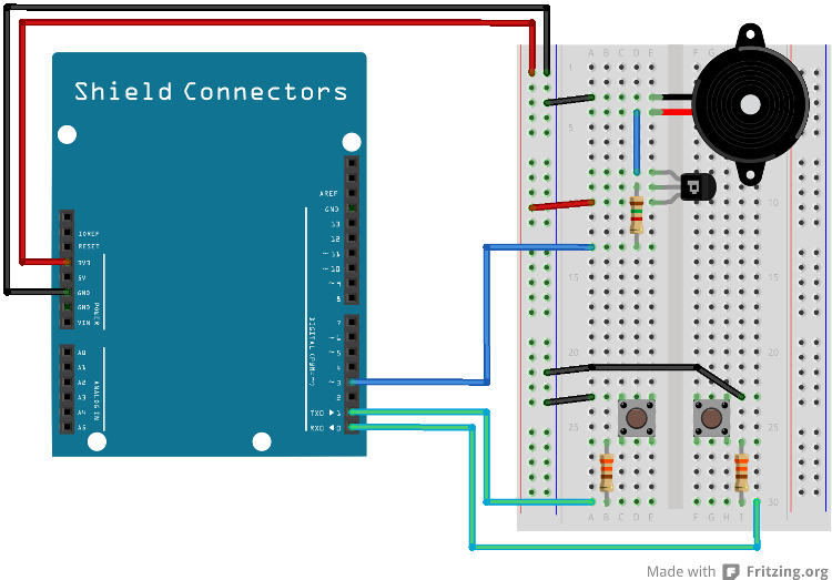
Mount the components on the breadboard and connect the breadboard to the LPC812 as show in the image below.

Information
A buzzer outputs a single frequency tone when driving current through it. A PNP-transistor is controlling the current through the buzzer. Pulling the base of the transistor low will enable the current through the transistor (and hence the buzzer). The series resistor on the transistor’s base connection limits the current (since signal D3/PIO0_8 will be close to ground, 0V, when pulled low by the LPC812 and a PNP bipolar junction transistor’s emitter-base voltage is fixed to around 0.7V).
Information
Note that the buzzer in the component kit might look different from the one in the picture below. Also note that both the PNP transistor and the buzzer are polarized components so it is important to turn them correct. Also note that the series resistor on the PNP base pin is 1.5 kohm (a different value than we have used so far).
The pin(s) are specified in the mbed library with the actual pin names as well as some useful aliases:
| Schematic Name | mbed Pin Name | Arduino Shield Alias | Desciption |
|---|---|---|---|
| PIO0_0 | P0_0 | D0 | Right push-button |
| PIO0_4 | P0_4 | D1 | Left push-button |
| PIO0_8 | P0_8 | D3 | Buzzer |
2) Description
In this experiment we will introduce logic between the input (push-buttons) and the output (a LED and a buzzer). Create a program that reads the two push-buttons and turn on the LED only when both are pressed simultaneous. Then change the logic so that the LED is on if only one of the push-buttons is pressed, but not both. The program structure will be the same as in the previous experiment, a forever loop. Read both inputs and then calculate the output value and output it. Add a DigitalOut for the buzzer:
DigitalOut buzzer(D3);
The buzzer can then be controlled in the same way as a LED. Setting it to 0 turns it on and 1 turns it off. Modify the existing code in this experiment so that the LED and the buzzer are controlled the same way (LED on = buzzer on).
3) Hardware
The same setup is used so no changes are needed.
3) Description
In this experiment we will introduce a state. Pressing the push-button shall turn the LED on. Pressing again will turn the LED off. Another way of expressing it is that the LED is toggled every time the pushbutton is pressed.
The structure of the program is outlined below. When the push-button first is pressed, the LED is toggled. Check the current state of the LED and inverse it. The recommended structure for this is to store the LED state in a separate variable. After having toggled the LED, the program must wait until the push-button has been released. If this last step is omitted, the LED would constantly toggle at a high rate as long as the push-button is pressed. That would not be a desirable solution since the LED can be in any state when the push-button is finally released.
#include "mbed.h"

DigitalOut myled(LED_RED);
DigitalIn  button(D0);

int main()
{
    bool ledOn = false;
    myled = 1;  // Turn LED off
    button.mode(PullUp); // Enable button

    // Enter forever loop
    while(1) {
        // Check if push-button is pressed (input is low)
        if (...) {
            // Toggle LED
            ...

            // Wait until push-button is released
            while(...);
        }
    }
}
You will probably notice that the LED will toggle a little more than expected. For example when releasing the push-button, sometimes the LED will not change state. This is because of contact bounce inside the push-button. The microcontroller is so fast so it will detect multiple presses/releases. In the next experiment you will find one way of dealing with this problem.
4) Hardware
The same setup is used so no changes are needed.
4) Description
In this experiment we will introduce the concept of sampling. In the previous experiments the outputs have been controlled as quickly as possible and the inputs have been read as often as possible. Although simple, it is often desirable to have more detailed control of the system behavior.
Sampling is a concept where the state of inputs is read at defined points in time, the sample period. Outputs are also controlled/changed at these points in time. More advanced systems can have many different rates active at the same time. Some inputs are read at high rate (for example 1000 Hz, once each 1 ms) while others are read at lower date, say 10 Hz (i.e., once each 100 ms). The used rate is a trade-off between workload for the microcontroller and how fast the input can change (or how fast the outputs must be controlled). A fast changing signal must for example be sampled often in order not to miss any important information.
In this experiment we shall sample the push-button with different sample rates. The forever-loop of the previous experiment is used. A delay function is introduced before checking push-button state. Use the wait function from the mbed library. If the delay is for example 100 ms, the effect is that the push-button is sampled at 10 Hz rate.
#include "mbed.h"

DigitalOut myled(LED_RED);
DigitalIn  button(D0);

int main()
{
    bool ledOn = false;
    myled = 1;  // Turn LED off
    button.mode(PullUp); // Enable button

    // Enter forever loop
    while(1) {
        // Delay a specified period of time (the sample period)
        wait(...);

        // Check if push-button is pressed (input is low)
        if (...) {
            // Toggle LED
            ...

            // Wait until push-button is released
            while(...);
        }
    }
}
Experiment with different delay settings / sample rates and see how fast you need the sample to pushbutton in order not to miss a quick push-button press.
As an added bonus, the problem with contact bounce is also handled when the delay was added. That is because the microcontroller is idling in the delay-loop while the contacts bounce.
Solution(s)
Import programlpc812_exp_solution_digital-in
Solutions for the Digital Input experiments for LPC812 MAX
Please log in to post comments.
