Important changes to forums and questions
All forums and questions are now archived. To start a new conversation or read the latest updates go to forums.mbed.com.
10 years, 1 month ago.
I want to build a LPC1114FDH28 for DIYers.

LPC1114FN28 is not always available from the retail market. Since it is designed for DIYers. I am considering to design a converter board for LPC1114FDH28, since they are pin-to-pin compatiable.
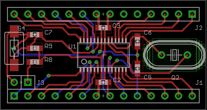
I have mounted necessary components including crystal, decouple capacitors, reset button.
However, I am struggling if I should mount ISP and SWD sockets on board, or any USB VCP on board. If I put everything on board, then it will become expensive and too crowded on board. And it will not be a converter but a mini board, instead.
Additionally, the xtal pins are left blank, since we don't use them any more.
Looking for any comments from DIYers/Geeks/Makers.
Question relating to:

2 Answers
10 years, 1 month ago.
An SWD socket can always be kept unpopulated, on the other hand I don't know if it would really be that useful compared to just using a normal pin. USB VCP is really handy, but then indeed it has little to do anymore with a converter. What are you planning to do with it? As in just distribute the gerber files, or sell them populated? Because soldering the LPC1114 will be enough of a challenge for most, soldering an FTDI chip in smallest package (which will porbably required with size constraints), is pretty much impossible for most.
Maybe if you have space, an extra connector with SWD signals, ground (obviously), power (optionally) and an UART. If you then use another mbed board for programming it (for example the seeedstudio ones), you could make yourself a connector to also do serial debugging via printf, and just let the board you use for programming also be USB<>Serial bridge. Personally I wouldn't place it on the board itself.
10 years, 1 month ago.
I will share the gerber file, as well as selling populated products. In order to fit the board into DIP28 (100mil pitch, 600mil width), we have to make some compromises between requirements, features and cost.
LPC1114FDH28 12MHz crystal + 2 caps Reset button with pull-up resistor and cap to GND ISP solder pad or jumper (smaller than button)
Connectors: SWD (RST/VCC/DIO/CLK/GND) Extra power rail connector (maybe replace XTAL pins)
Other features will be available on breadboard: LDO RX/TX pins USB VCP
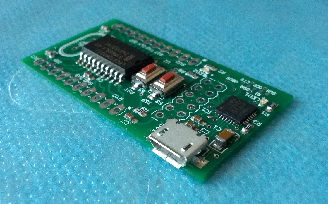
BTW, I have made a mini board with LPC812 and CP2102. The CP2102 is a breakout board.  Although it can be used in breadboard, but it is not a standard 600mil width, but 700mil width. Check it out here.
Since LPC1114FN28 is designed for DIYer and breadboard, so I want to make a simpler/smaller board for them, which add limited cost on LPC1114FDH28. The total cost is comparable to retail price of DIP28 version.
Of course, if they can accept higher cost, we can use smaller components with higher density. According to my estimation. A retail price of DIP28 mini board will be around 1215USD.