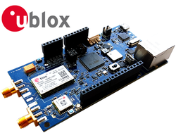
u-blox C030-U201 IoT Starter Kit
The u-blox C030-U201 2G/3G mbed-enabled Internet of Things (IoT) Starter Kit is a versatile development platform that allows quick prototyping of a variety of applications for low-power Internet of Things (IoT).
Pinout

Unboxing C030
Features
u-blox SARA-U201 HSPA/GSM Module
- Global 2G/3G coverage
- 2G Bands: 850, 900, 1800, 1900
- 3G Bands: 800, 850, 900, 1900, 2100
u-blox MAX-M8C Concurrent GNSS Receiver Module
- Receives up to 3 GNSS technology out of GPS, Galileo, GLONASS, and BeiDou
STMicroelectronics STM32F437VG MCU
- High-performance ARM® Cortex™-M4 running up to 180MHz
- 1024 KB on-chip Flash
- 256 KB on-chip SRAM + 4 KB Battery backed up on-chip SRAM
- 192 KB of on-chip SRAM for Application use
- 64 KB of on-chip SRAM as Closely Coupled Fast RAM
- 10/100 Mbps Ethernet MAC
- Cryptographic acceleration for Internet message protocols
- True random number generation, CRC calculation unit
Interfaces and Electrical Data
- Integrated eUICC including International Data Roaming Cellular Connectivity by JT® JTGlobal with 50Mbytes of data for the first 90 days
- On-board ST-Link/V2-1 debugger/programmer with SWD connector
- micro USB with mbed Interface
- ST-Link/V2-1 standalone development and debug capability
- USB re-enumeration; Virtual COM port, Mass Storage Device and Debug Port
- 5V from ST-Link/V2-1 Debug USB VBUS, 3.3V operation
- (CMSIS-DAP variant of the FW with extended features will be available in the future)
- On-board TI® bq24295 Single Cell LiPo Battery Charger and TI® bq27441-G1 Battery Fuel Gauge
- Molex® SPOX™ 5268-03A LiPo Battery connector. Supports battery types like BAK –LP-503759-IS-3 (battery is not included)
- On-board SiLabs® CP2105 USB to Dual UART Bridge as Serial USB Sniffer
- Alternative to ST-Link/V2-1 Virtual COM Port when ST-LINK/V2-1 is not used/available
- Alternative to Main Supply and Debug USB 5V VBUS inputs
- Sniffing serial communication between the Host MCU and the Cellular Module
- Drivers could be downloaded from here
- RGB User LED, and two push buttons: User and Reset
- SDCard Socket for file storage
- SMA RF connectors for 50 Ohm Cellular and GNSS Active antennas
- Ethernet RJ45 connector
- Arduino® UNO R3 compatible header connector with
- 6 analog inputs,
- 8 PWM capable outputs,
- 22 GPIOs,
- 1 x SPI,
- 1 x I2C,
- 1 x UART with HW flow control option (RTS, CTS)
Utilising Arduino VIN Input Pin
Ensure that VIN voltage level does not exxceed the cellular module input voltage limitations. Reverse polarity and exceeding the supply voltage limits can cause a permanent damage.
Please consult your u-blox representative for further details.
external power supply and/or LiPo battery is recommended
Due to the USB current limitation, optimal RF performance can be achieved only by supplying the board either through the "Aux 5V USB" connector or the VIN pin of the Arduino® UNO R3 interface. Other alternative is to use a LiPo Battery connected through the "LiPo Battery" connector. Please refer to Power Supply and LiPo Battery section below.
International Data Roaming by JT
The C030-U201 IoT Starter Kits come with International Data Roaming bundled with 50 MBytes of data for the first 3 months .
The International Data Roaming service is provided by JT . To turn on the International Data Roaming service, please register your board's eUICC(Embedded SIM) IMSI through JT IoT Registration web site.
Information
How to find C030-U201 IMSI Number
The eUICC(Embedded SIM) IMSI number is written on the label at the back of the C030-U201. The IMSI number is also coded on the QR-Code label on top of the Ethernet connector of the C030-U201.
If the IMSI number cannot be read from these labels, the example program for reading the modem IMEI and eUICC/SIM IMSI could be used. The example prints out the IMEI and IMSI numbers of the board to the serial debug console.
Import programexample-reading-imei-imsi
Example to read the modem IMEI and eUICC/SIM IMSI
Last commit 11 Jun 2019 by ![]() u-blox
u-blox
Block Diagram

Power Supply and LiPo Battery
During the RF transactions, SARA-U201 module of C030-U201 Application Board demands higher currents than a USB 2.0 Master Port could provide. If the C030-U201 Application Board is powered from a single USB 2.0 port, a Brown Out could be experienced during RF transactions. This situation is observed as premature board reset and/or application interruption. To overcome such situation, the C030-U201 Application Board could be powered with a high current PSU through purpose built "Aux 5V USB" connector. Another, solution is to connect a LiPo battery to the "LiPo Battery Connector"
Recommended 3A 5V USB Power Supplies for the UK , the North America, and the Europe
Recommended LiPo Battery from Dynamis https://www.dynamis-batterien.de/
Recommended LiPo Battery BAK –LP-503759-IS-3 from Farnell UK, Farnell Germany
Documentation
C030 Application Board User Guide
C030-U201 Application Board Schematics
Module current instrumentation
There are provisional current instrumentation circuits for both Cellular and GNSS modules. Currently,the instrumentation functions are not utilized and supported
See also
C030 Prime Cell Battery Shield
Approvals
Information
C030-U201 European conformance CE mark
The C030-U201 application board has been evaluated against the essential requirements of the 2014/53/EU Radio Equipment Directive. In order to satisfy the essential requirements of the 2014/53/EU Radio Equipment Directive, the device is compliant with the following standards:
- Radio Frequency spectrum use (Article 3.2):
- EN 301 511
- EN 301 908-1
- EN 301 908-2
- EN 303 413
- Electromagnetic Compatibility (Article 3.1b):
- EN 301 489-1
- EN 301 489-19
- EN 301 489-52
- Health and Safety (Article 3.1a)
- EN 62368-1
- EN 62311 and EN 62479
The conformity assessment procedure for C030-U201 application boards, referred to in Article 17 and detailed in Annex III of Directive 2014/53/EU, has been followed. Thus, the following marking is included in the product:

There are no restrictions for the commercialization of the C030-U201 application boards in all the countries of the European Union.
Radiofrequency radiation exposure Information: this equipment complies with radiation exposure limits prescribed for an uncontrolled environment for fixed and mobile use conditions. This equipment should be installed and operated with a minimum distance of 20 cm between the radiator and the body of the user or nearby persons. This transmitter must not be collocated or operating in conjunction with any other antenna or transmitter except as authorized in the certification of the product.
The gain of the system antenna(s) used for C030-U201 application boards (i.e. the combined transmission line, connector, cable losses and radiating element gain) must not exceed 2.96 dBi (900 MHz, i.e. GSM 900 or UMTS FDD-8 band), 7.85 dBi (1800 MHz, i.e. GSM 1800 band), 11.84 dBi (2100 MHz, i.e. UMTS FDD-1 band) for mobile and fixed or mobile operating configurations.
You need to log in to post a discussion
Questions
 Yonghong Zhang
 6 years, 8 months ago
To compile a program for this board using Mbed CLI, use ublox_c030_u201 as the target name.
Silicon Partner
ST
A world leader in providing the semiconductor solutions that make a positive contribution to people’s lives, both today and in the future.
 Mbed Enabled
- Advanced
- Baseline
Mbed OS support
- Mbed OS 5.10
- Mbed OS 5.11
- Mbed OS 5.12
- Mbed OS 5.13
- Mbed OS 5.14
- Mbed OS 5.15
- Mbed OS 5.6
- Mbed OS 5.7
- Mbed OS 5.8
- Mbed OS 5.9
Example programs