Arch Cookbook
 Visweswara R.
0
replies
Visweswara R.
0
replies
"Anyone can cook." - Gusteau's (a character in Ratatouille)
This cookbook is a starting point to work with Seeedstudio Arch platform. It introduces the platform with step by step examples by using Seeedstudio Grove modules. The cookbook is written with beginners in mind and assumes no prior experience in mbed API. This book expects a basic knowledge of C programming language. mbed API and programs are written C++ language. Although not essential to understand the programs, it is better you understand how to create an object for a class and how to use member functions.
If you are beginner, who is learning Embedded Systems and programming in C/C++ - import and execute the examples programs one by one by following the procedure listed in each recipe. You can skip all other fine details presented in the beginning.
Happy Programming :)
Warning
This is an unfinished work. Please wait until at-least a draft version is released.
Arch platform
Seeedstudio Arch is a mbed enabled platform based on NXP's LPC11U24 microcontroller. This platforms comes with header pins whose footprint are compatible with Arduino shields. The two on-board Grove connectors can be interfaced with numerous Grove based sensors, actuators and display modules.
Arch platform can be easily programmed over USB using the LPC11U24's inbuilt ISP driver. Unlike mbed LPC11U24, Arch platform does not come with mbed interface chip. Hence, an additional Arch board has to be used to debug the target using CMSIS-DAP.
Features
- Shields compatible header pins
- Two Grove connectors
- A large number of grove modules
- Drag-n-drop programming
- NXP LPC11U24 MCU
- Low power ARM Cortex-M0 Core
- 48MHz, 32KB Flash, 8KB RAM, 4KB EEPROM
- USB Device, 2xSPI, UART, I2C
Hardware

DigitalOut/In
All pins with light blue coloured label can be used as DigitalOut/In interface.
Four on board LEDs D1-D4 are connected to port pins as shown in the table below. These can be used with LED1, LED2, LED3 and LED4 pseudonym instead of port pin name.
| Port Pin | Alias name |
|---|---|
| P1_8 | LED1 |
| P1_9 | LED2 |
| P1_10 | LED3 |
| P1_11 | LED4 |
PwmOut
Pins labelled as PwmOut (i.e magenta coloured label) are possible outputs that can be routed from timers to generate PWM. The following table lists how the pins are connected to timers. The period value is same for PwmOut pins sharing a single timer.
| Timer/Register | Routing Pin |
|---|---|
| CT16B0/MR0 | P0_8 and P1_13 |
| CT16B0/MR1 | P0_9 and P1_14 |
| CT16B0/MR2 | P0_10 and P1_15 |
| CT16B1/MR0 | P0_21 |
| CT16B1/MR1 | P0_22 and P1_23 |
| CT32B0/MR0 | P0_18 and P1_24 |
| CT32B0/MR1 | P0_19 and P1_25 |
| CT32B0/MR2 | P0_1 and P1_26 |
MR3 register is used for period setting and MR1/2/3 are used for pulse-width (i.e duty cycle).
UART
The TXD or RXD labelled pins (i.e yellow coloured label) are possible routing pins for one UART port. At a time, one TXD and one RXD pin can be configured for the UART.
For more information on hardware see Seeeduino Arch page.
Getting started
Recipe 1: Blinking a LED
Ingredients
- Seeedstudio Arch board
- Micro-USB cable
- Access to internet and online mbed compiler.
Procedure
- Import the following Arch_GPIO_Ex1 program into online mbed compiler.
- Select Seeedstudio Arch as target platform (navigate to top-left corner of online compiler).
- Click Compile and Download button.
- You browser will download Arch_GPIO_Ex1_LPC11U24.bin file.
- Connect Arch board to PC using a micro-USB cable.
- Press the reset button longer(at-least 2 seconds) and release.
- You must see a USB drive being detected by you OS.
- Copy the Arch_GPIO_Ex1_LPC11U24.bin to that USB drive.
- Press and release the reset button very quickly.
- You have flashed your first program onto Arch board.
Import program
00001 #include "mbed.h"
00002
00003 /* Configure a GPIO pin as output for controlling a LED. 'led' is user assigned name and
00004  'LED1' is a internal name given to a port pin P1_8 in this Arch platform. */
00005 DigitalOut led(LED1);
00006
00007 int main()
00008 {
00009     while(1) {
00010         led = 1;    // Switch ON the LED.
00011         wait(0.5);  // Wait for 0.5 Seconds.
00012         led = 0;    // Switch OFF the LED.
00013         wait(0.5);  // Wait for 0.5 Seconds.
00014     }
00015 }
The above program uses mbed interface DigitalOut and mbed built-in function wait(). LED1 is an pseudonym given to port pin P1_8. LED1 is labelled D1 in the Arch board. The state of LED1 is changed writing either 0 or 1 to 'led'. The mbed wait() function produces a delay in seconds. The state of the 'led' is continuous toggled every 0.5 seconds inside the endless *while()* loop.
The features and functions present in DigitalOut are documented in DigitalOut page in handbook. Similarly the wait() function is documented in wait page in handbook
Variation
Let us rewrite the above program using alternate APIs provided DigitalOut and wait.
Import program
00001 #include "mbed.h"
00002
00003 /* Configure a GPIO pin as output for controlling a LED. 'led' is an user assigned name and
00004  'LED1' is an internal name given to a port pin P1_8 in this Arch platform. */
00005 DigitalOut led(LED1);
00006
00007 int main()
00008 {
00009     while(1) {
00010         led.write(1);    // Here, DigitalOut -> write() function is used to set the ouput high.
00011         wait_ms(500);    // Wait for 0.5 Seconds. The time is specified in milli-seconds using wait_ms() function.
00012         led.write(0);    // Switch OFF the LED.
00013         wait_us(500000); // Wait for 0.5 Seconds. The time is specified in micro-seconds using wait_us() function.
00014     }
00015 }
Instead of led = in the Ex1 program, we have used led.write() function which essential does the same operation. Here, wait() is replaced by wait_us(). The delay time is specified in micro seconds instead of seconds in this function.
Recipe 2: Playing with Digital Input
Ingredients
In addition to things listed in Recipe 1 we require
- Grove - Button
Procedure
- Connect Grove - Button to on-board grove connector marked UART.
- Import the following Arch_GPIO_Ex3 program into online mbed compiler.
- Build and upload the program to Arch platform. (follow procedure listed in Recipe 1)
This program keeps the LED1 on as long as the button is pressed.
Import program
00001 #include "mbed.h"
00002
00003 DigitalOut led(LED1);    // Configure LED1 pin as output
00004 DigitalIn button(P1_14); // Configure P1_14 pin as input
00005
00006 int main()
00007 {
00008     while(1) {
00009         led.write(button.read());    /* read the state of input port pin P1_14 and write it to output port pin LED1*/
00010     }
00011 }
We use DigitalIn interface to read the status of a tactile switch connected to port pin P1_14. The button.read() function returns a value 1 if button is pressed and 0 if released. This value is written to LED1 port pin using led.write().
More information on this new module is available at DigitalIn handbook page.
Recipe 3: Single Instruction Multiple Output
Ingredients
- Same as Recipe 1.
Procedure
- Build and upload the program to Arch platform. (follow procedure listed in Recipe 1)
The following program uses one variable to modify a set of 4 LEDs with BusOut interface. The LED1 to LED4 counts up 4-bit binary value one by one with half-a-second delay. BusOut interface comes handy while sending data to devices with parallel ports like LCDs.
Import program
00001 #include "mbed.h"
00002
00003 BusOut onboardLEDs(P1_8,P1_9,P1_10,P1_11); /*P1_8 - P1_11 are LED1 - LED4*/
00004
00005 int main()
00006 {
00007     int i;
00008     while(1) {
00009         for(i=0; i<16; i++) {
00010             onboardLEDs.write(i); /* LED1 is LSB  and LED4 is MSB*/
00011             wait(0.5);
00012         }
00013
00014     }
00015 }

Recipe 4: Analog matters
Ingredients
In addition to things listed in Recipe 1 we require
- Grove - Potentiometer
Procedure
- Connect middle SIG pin of Grove - Potentiometer to P0_11, other two pins to GND and 3.3V
- Build and upload the program to Arch platform. (follow procedure listed in Recipe 1)
The rate of blinking of the LED is controlled by the analog value read from the potentiometer.
Import program
00001 #include "mbed.h"
00002
00003 AnalogIn pot(P0_11);   /* Potentiometer middle pin connected to P0_11, other two ends connected to GND and 3.3V */
00004 DigitalOut led(LED1);  /* LED blinks with a delay based on the analog input read */
00005
00006 int main()
00007 {
00008     float ain;   /* Variable to store the analog input*/
00009
00010     while(1) {
00011         ain = pot.read(); /* Read analog value (output will be any value between 0 and 1 */
00012         led = 1;          /* Switch ON LED        */
00013         wait(ain);        /* Wait for 'ain' Seconds (maximum delay is 1 seconds)*/
00014         led = 0;          /* Switch Off LED       */
00015         wait(ain);        /* Wait for 'ain' Seconds (maximum delay is 1 seconds)*/
00016     }
00017 }
Recipe 5: Temperature Sensing
Ingredients
In addition to things listed in Recipe 1 we require
- Grove - Temperature Sensor
Procedure
- Connect SIG pin of Grove - Temperature Sensor to P0_11, other two pins to GND and 3.3V
- Build and upload the program to Arch platform. (follow procedure listed in Recipe 1)
The room temperature is displayed as LED blinks. LED4 blinks corresponding to tens place of temperature value(in deg C) and LED1 blinks according to units place.
Import program
00001 #include "mbed.h"
00002
00003 AnalogIn thermistor(P0_11);   /* Thermistor output connected to P0_11 */
00004
00005 DigitalOut tensplaceLED(LED4);  /* This led blinks as per tens place of temperature value(in deg C) */
00006 DigitalOut unitsplaceLED(LED1); /* This led blinks as per units place of temperature value(in deg C) */
00007
00008 int main()
00009 {
00010     unsigned int a, beta = 3975, units, tens;
00011     float temperature, resistance;
00012
00013     while(1) {
00014         a = thermistor.read_u16(); /* Read analog value */
00015
00016         /* Calculate the resistance of the thermistor from analog votage read. */
00017         resistance= (float) 10000.0 * ((65536.0 / a) - 1.0);
00018
00019         /* Convert the resistance to temperature using Steinhart's Hart equation */
00020         temperature=(1/((log(resistance/5000.0)/beta) + (1.0/298.15)))-273.15;
00021
00022         units = (int) temperature % 10;
00023         tens  = (int) temperature / 10;
00024
00025
00026         for(int i=0; i< tens; i++)
00027         {
00028              tensplaceLED = 1;
00029              wait(.200);
00030              tensplaceLED = 0;
00031              wait(.200);
00032         }
00033
00034         for(int i=0; i< units; i++)
00035         {
00036              unitsplaceLED = 1;
00037              wait(.200);
00038              unitsplaceLED = 0;
00039              wait(.200);
00040         }
00041
00042         wait(0.5);
00043     }
00044 }
00045
Recipe 6: Working with Serial LCD
Ingredients
In addition to things listed in Recipe 1 we require
- Grove - Serial LCD
Procedure
- Connect Tx of LCD to Rx of Arch board, Rx of LCD to Tx of Arch Board
- Connect GND of LCD and Arch Board
- Connect Vcc of LCD to 5V of Arch board (Yes! Serial LCD works at 5V)
- Build and upload the program to Arch platform. (follow procedure listed in Recipe 1)
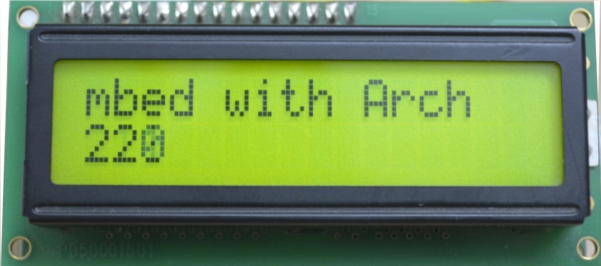
The following program demonstrates printing text and numbers :
Import program
00001 #include "mbed.h"
00002 #include "SerialLCD.h"
00003
00004 SerialLCD lcd(P1_13, P1_14);  /* Grove Serial LCD is connected to UART Tx and Rx pins*/
00005
00006 int main() {
00007     int a=0;
00008     char strBuffer[16];
00009
00010     lcd.begin();                 /* initialize Serial LCD communication. */
00011     lcd.print("mbed with Arch"); /* print text */
00012
00013     while (1) {
00014
00015         lcd.setCursor(0, 1);         /* set cursor at 0th column and 1st row */
00016         sprintf(strBuffer, "%d", a); /* prepare a string buffer to print number */
00017         lcd.print(strBuffer);        /* print the string buffer */
00018         wait(0.1);                   /* wait 100ms */
00019         a++;
00020     }
00021 }
Modifying the Thermistor program to use LCD
- Apart from Serial LCD connection, connect Grove - Temperature similar to Recipe 5
The following program display temperature in deg C using LCD.
Import program
00001 #include "mbed.h"
00002 #include "SerialLCD.h"
00003
00004 SerialLCD lcd(P1_13, P1_14);  /* Grove Serial LCD is connected to UART Tx and Rx pins*/
00005
00006 AnalogIn thermistor(P0_11);   /* Thermistor output connected to P0_11 */
00007
00008 int main()
00009 {
00010     char strBuffer[16];
00011     unsigned int a, beta = 3975;
00012     float temperature, resistance;
00013
00014     lcd.begin();                 /* initialize Serial LCD communication. */
00015
00016     while(1) {
00017         a = thermistor.read_u16(); /* Read analog value */
00018
00019         /* Calculate the resistance of the thermistor from analog votage read. */
00020         resistance= (float) 10000.0 * ((65536.0 / a) - 1.0);
00021
00022         /* Convert the resistance to temperature using Steinhart's Hart equation */
00023         temperature=(1/((log(resistance/5000.0)/beta) + (1.0/298.15)))-273.15;
00024
00025         sprintf(strBuffer, "Tmp %4.2f deg C", temperature); /* prepare a string buffer to print number */
00026         lcd.setCursor(0, 0);  /* set cursor at 0th column and 0st row */
00027         lcd.print(strBuffer); /* print the string buffer */
00028
00029         wait(0.5);
00030     }
00031 }
Please log in to post comments.
Arch Cookbook
Cookbook to use Seeedstudio Arch platform
Page owner: Visweswara R
Created 05 Sep 2013.
Last updated 24 Oct 2013