DrawBot
Alejandro and I thought it would be interesting to build a drawing robot for the final project in ECE 4180 at Georgia Tech. We planned to suspend a pen from two stepper motors and draw pictures by controlling the rotation of the motors, Starting from this rough idea, we ended up with a drawing robot that could draw recognizable images, and even write out messages!
Import programDrawBot
Final code for our 4180 Drawing Robot!
Electronics
Motor Control
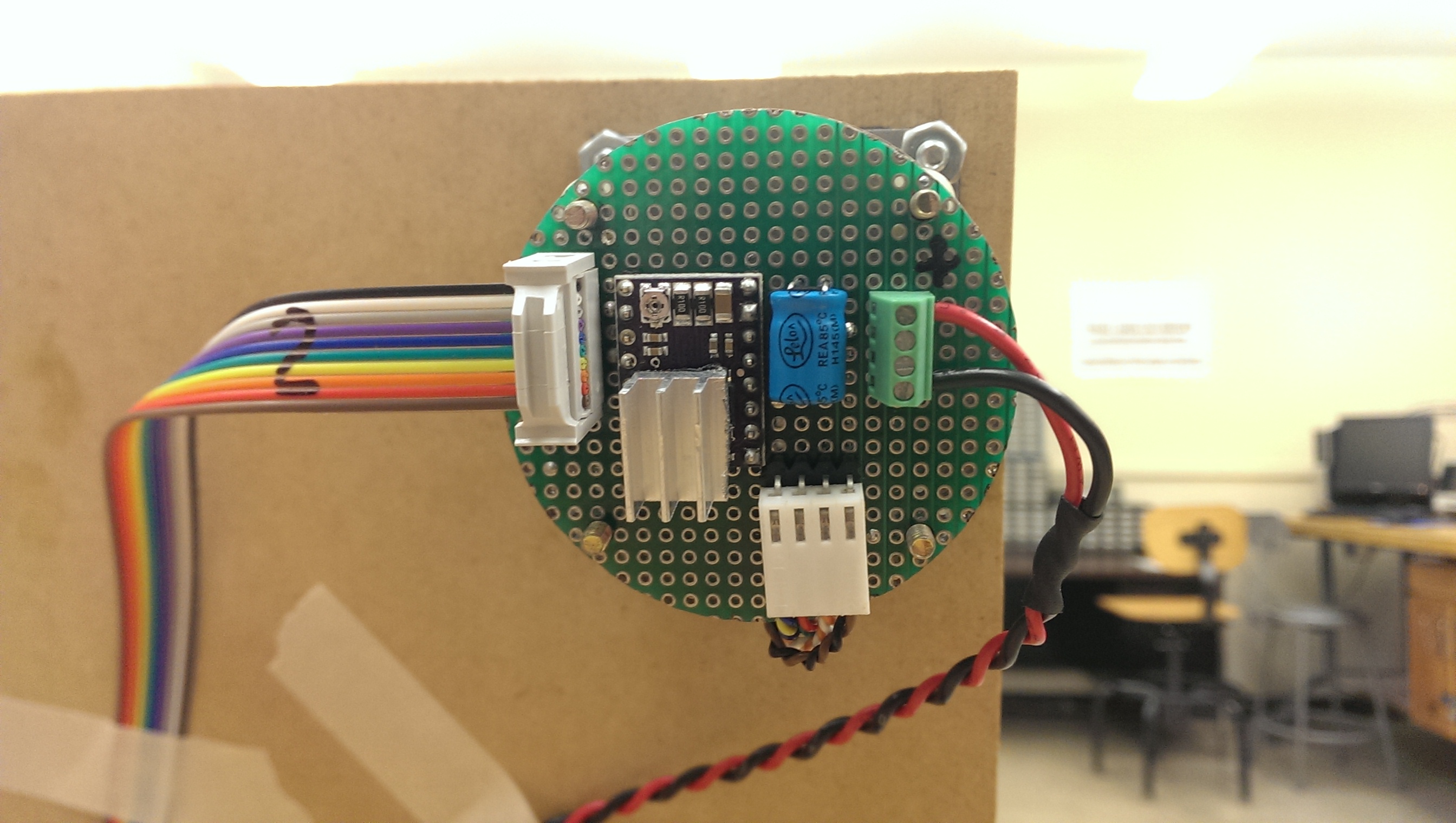
We started with the motors. We used 1.8 degree per step stepper motors pulled from the junk pile, and we bought DRV8825 stepper motor breakout boards from Pololu to control them. These modules are convenient because they can handle up to 2.2 A per coil with a heatsink, and they have an onboard 5v regulator for the logic power supply.
The motor controllers can be purchased here.
We cut out circular pieces of perf board, wired up the stepper motor controllers, and mounted them on the backs of the motors. We used the schematic provided on the pololu page to wire up the DRV8825's. The red and black wires provide 20v for the motors, and the ribbon cable carries the control signals to the MBED (step, direction, sleep/reset, enable, MS0, MS1, MS2, gnd).

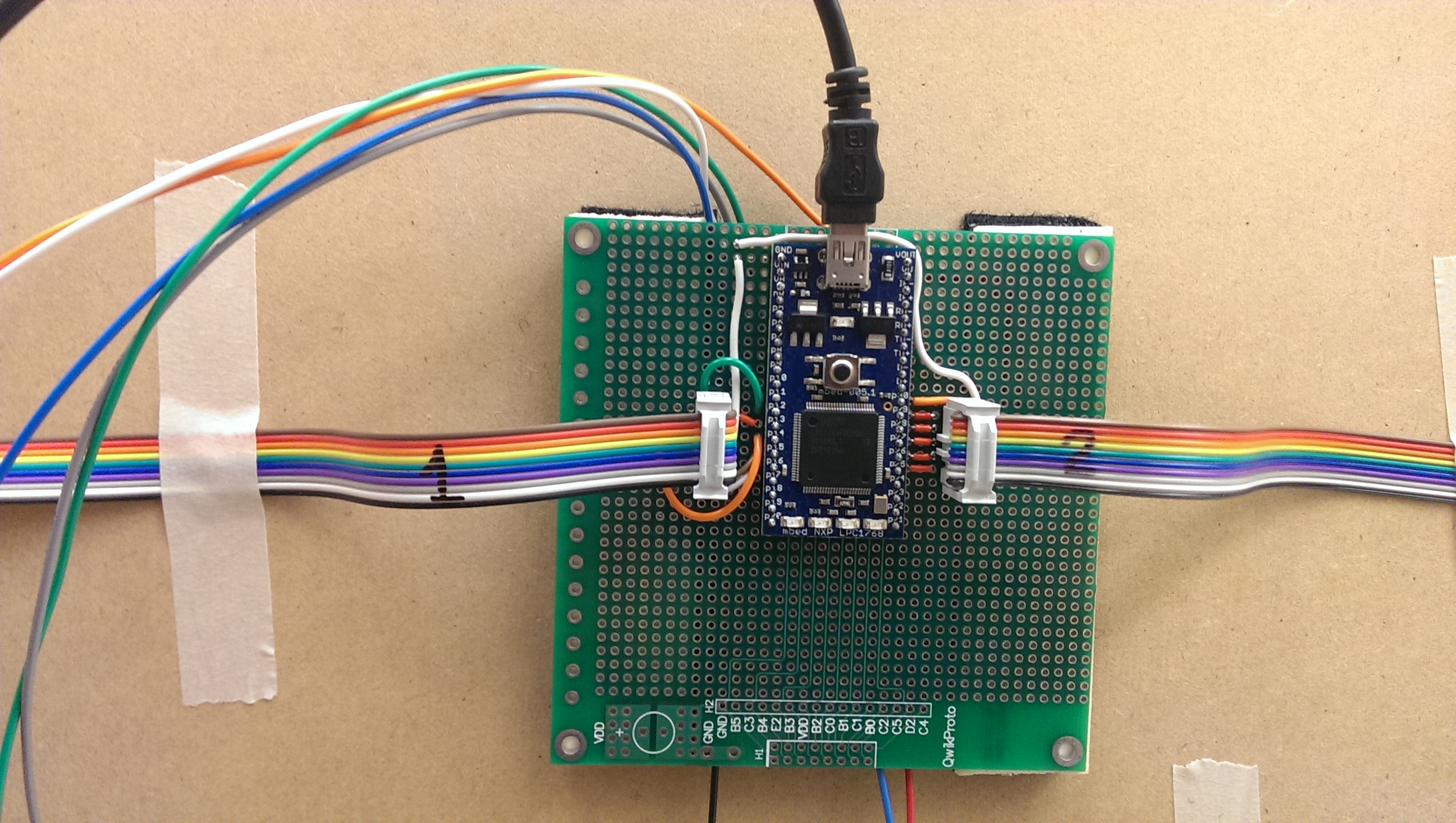
MBED
The MBED orchestrates the entire drawing process. It receives GCODE commands from a laptop over the USB Serial connection. It then parses the GCODE and sends appropriate motor control signals out to the stepper motor controllers via the ribbon cables.

Hardware
We mounted the stepper motors in the top corners of a 4'x2' piece of MDF, andd we used these pulleys and toothed belts from McMaster-Carr.
Pulleys: http://www.mcmaster.com/#1375k52/=rrespq
Belts: http://www.mcmaster.com/#1679k684/=rresq1
The 1/8 inch belts were probably a little too light for this application, as they have a tendency to vibrate while the bot is drawing. Performance would likely be improved by using a heavier belt.
Pen Carrier
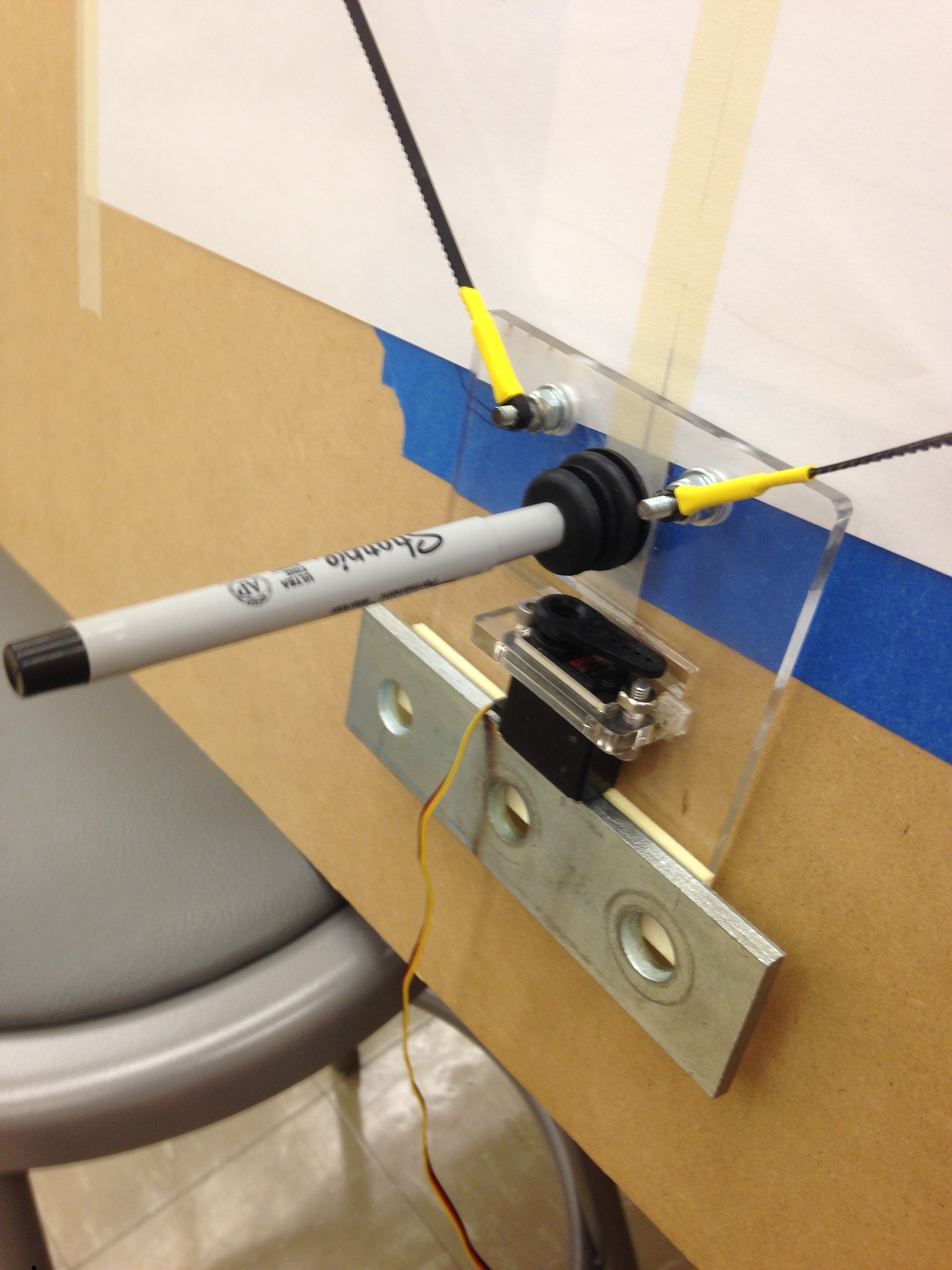
The pen carrier is made from laser cut acrylic. It has a miniature servo mounted to it, so we could select whether or not the pen makes contact with the drawing surface. The large steel weight attached to the bottom damps vibrations and pushes the pen against the drawing surface.

Code
Parsing Stage
Using Visual Studio 2013, a C++ application was written that parses a provided GCODE file. The aplication scans the connected serial devices and it connects to the Mbed to send the GCODE commands. It is implemented as a simple state machine in which the application opens the connection, parses each line of commands from the GCODE file, sends it to the Mbed, and waits for a special FEEDME signal sent back before sending the next command.
The Mbed is running the MODSERIAL library which allows to buffer the incoming data until a specific character is received (the '/0' character in this case) indicating the end of the current command. When the special character is received, it means that a whole GCODE command has been buffered and a callback function is invoked on the Mbed that stores the command in a G_cmd structure.
// struct to hold a Gcode command
typedef struct {
    int G;
    float X;
    float Y;
    float Z;
    float F;
    float I;
    float J;
}G_cmd;
This structure is used to fill a command array from which the Mbed will draw commands during the drawing phase. After each command is fetched, the serial buffer is flushed and the FEEDME signal is sent from the Mbed to the C++ application to indicate the device is ready to receive another command. When the C++ application has finished reading the file it sends an END_OF_TRANSMISSION character to the Mbed to indicate that the parsing is over and the drawing stage may begin.
Drawing Stage
As previously mentioned, on the MBED side GCODE commands are buffered and parsed into usable structs by calls made to the gCodeParser library. Depending on the command, one of several actions may occur. G00 and G01 both call the DrawBot::line_safe() function to draw a straight line from the current position to the new position specified by the X, Y, and Z fields in the GCODE command. The DrawBot::line_safe() function splits long lines into shorter lines for improved accuracy, and calls the DrawBot::line() function to actually move the pen to the new positions. The DrawBot::line() function uses Bresenham's algorithm to determine when and in which direction to step the motors. The G02 and G03 commands both draw arcs, so when the MBED sees a G02 or G03, it calls DrawBot::arc(). The DrawBot::arc() function splits arcs into line segments and calls DrawBot::line() to draw them. The INCHES_PER_SEG #define sets the maximum length of each line segment in an arc.
Line code
The following code segment is the DrawBot::line() function. It uses Bresenham's line algorithm to decide when to step the motors to draw a line from (px, py) to (newx, newy). Before it runs the line algorithm, it calls DrawBot::IK() to convert the x and y coordinates into belt lengths.
void DrawBot::line(float newx, float newy) {

    pc.printf("LINE: (%f, %f) -> (%f, %f)\n",px,py,newx,newy);

    long L1, L2, oldL1, oldL2;
    IK(px*STEP_PER_INCH, py*STEP_PER_INCH, oldL1, oldL2);
    IK(newx*STEP_PER_INCH, newy*STEP_PER_INCH, L1, L2);

    long d1=L1-oldL1;
    long d2=L2-oldL2;
    int dir1=d1>0?1:0;
    int dir2=d2>0?1:0;
    d1=abs(d1);
    d2=abs(d2);

    long i;
    long over = 0;

    if(d1>d2) {
        for(i=0;i<d1;++i) {
          mL->one_step(dir1);
          over+=d2;
          if(over>=d1) {
            over-=d1;
            mR->one_step(dir2);
          }
          pause(step_delay);
        }
    } else {
        for(i=0;i<d2;++i) {
          mR->one_step(dir2);
          over+=d1;
          if(over>=d2) {
            over-=d2;
            mL->one_step(dir1);
          }
          pause(step_delay);
        }
    }

    px=newx;
    py=newy;
}
Please log in to post comments.
