DAPLink bootloader updates with external debug probe
If you read the blog post DAPLink bootloader update and identified that your board is in a bricked state you'll need an external debug probe to reinstall the bootloader image . Not to worry, if you have a spare NXP FRDM development board you can use it to restore the bootloader image on the other board!
Required items
- External debug probe or NXP FRDM development board
- Python 2.7 and pyOCD
- 10 pin debug cable.
Step 1: Locate an external debug probe
There are a few different options when it comes to using an external debug probe to restore the bootloader. One option is to use a LPC11U35 based debug probe such as the SWDAP. Alternatively, it is possible to use another NXP FRDM board to program the other board. Depending on the board, you may need to solder a 10-pin SWD header and set jumpers or cut traces. Here are some tutorials on how to modify the FRDM-K64F, FRDM-KL25Z and FRDM-KL43Z although others should be similar.
DAPLink bootloader update images are available for download from the table below. These are built with the same application offset address that the boards originally shipped with (20k or 32k), so the existing DAPLink interface firmware or third party interface firmware will be compatible. There may be more compatible boards than currently listed . Ask a question or start a discussion at the end of this blog post if you have a board not listed and need help restoring the bootloader.
Step 2. Download updated DAPLink bootloader image
To download the bootloader image for a specific board, click on the corresponding link in the table below.
| Board | DAPLink bootloader image |
|---|---|
| FRDM-K64F FRDM-KL82Z RedBearLab-nRF51822 v1.0 RedBearLab-BLE-Nano v1.0 | 0244_k20dx_bl_0x5000.bin |
| FRDM-K22F FRDM-K28F FRDM-K82F FRDM-KW24D FRDM-KL28Z TWR-KL28Z FRDM-KE15Z TWR-KE18F HVP-KE18F MTS-xDot-L151CC | 0244_k20dx_bl_0x8000.bin |
| Nordic-nRF51-DK Nordic-nRF52-DK Nordic-nRF51-Dongle Nordic-nRF51822 | 0244_sam3u2c_bl_0x5000.bin |
Step 3: Install Python and pyOCD
pyOCD is an open source Python-based library for programming and debugging ARM Cortex-M microcontrollers over the CMSIS-DAP debug protocol. With Python 2.7 installed, you can install pyOCD using the following command. If you are using a Linux machine you'll need to install as superuser.
pip install pyOCD
Step 4: Connect external debug probe
Locate the 10-pin header associated with the boards k20dx interface MCU. Usually, this is the header near the debug USB port. Connect the 10-pin debug cable to this header such that pin 1 of the header connects to the red wire on your debug cable. The pin numbering is printed on the silkscreen of the board for reference. In the image below, we drew a green square around the k20dx interface MCU and a green circle around pin 1 of its corresponding 10-pin header.

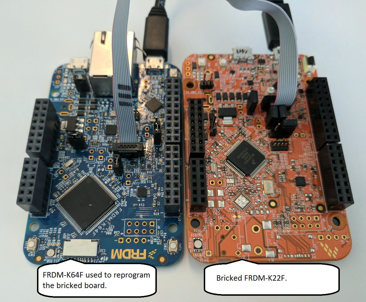
Next, connect the debug probe to the board requiring the bootloader to be restored. Ensure that both the debug probe and the other board are plugged into your computer using a USB cable for power. The image below is an example of how to use a FRDM-K64F as a debug probe to restore the bootloader on a FRDM-K22F development board.

Step 5: Flashing the updated bootloader
Now we're ready to restore the DAPLink bootloader using the pyOCD flashtool. If you are using a Linux machine you'll need to run as superuser.
Note: If you have multiple devices connected to your computer, the console prompts you to specify which device pyOCD uses as the debug probe. Choose the ID number that represents your debug probe and then hit Enter.The output looks similar to the following:
pyocd-flashtool <path to bootloader image> -t k20d50m
id => usbinfo | boardname
0 => NXP LPC800-MAX [k20d50m]
1 => FRDM-K64F [k20d50m]
input id num to choice your board want to connect

INFO:root:DAP SWD MODE initialised
WARNING:root:K20D50M in secure state: will try to unlock via mass erase
WARNING:root:K20D50M secure state: unlocked successfully
INFO:root:ROM table #0 @ 0xe00ff000 cidr=b105100d pidr=4000bb4c4
INFO:root:[0]<e000e000:SCS-M3 cidr=b105e00d, pidr=4000bb000, class=14>
WARNING:root:Invalid coresight component, cidr=0x0
INFO:root:[1]<e0001000: cidr=0, pidr=0, component invalid>
INFO:root:[2]<e0002000:FPB cidr=b105e00d, pidr=4002bb003, class=14>
WARNING:root:Invalid coresight component, cidr=0xb1b1b1b1
INFO:root:[3]<e0000000: cidr=b1b1b1b1, pidr=b1b1b1b1b1b1b1b1, component invalid>
WARNING:root:Invalid coresight component, cidr=0x0
INFO:root:[4]<e0040000: cidr=0, pidr=0, component invalid>
INFO:root:CPU core is Cortex-M4
INFO:root:6 hardware breakpoints, 4 literal comparators
INFO:root:4 hardware watchpoints
[====================] 100%
INFO:root:Programmed 131072 bytes (128 pages) at 25.32 kB/s
Step 6: Install an interface firmware application
You can now install any interface firmware version but we suggest getting the latest DAPLink interface firmware. Just enter the board name in the interface firmware update section to get the latest. Then, with the device mounted as MAINTENANCE, open the device's root directory then drag-and-drop the firmware update into this directory. When the file copy operation completes the board will unmount and remount as DAPLINK or the name of the board and the update is complete.
Conclusions
Your boards should now be updated and in good working order. To check the version of the DAPLink bootloader or interface firmware look in the DETAILS.TXT when the device is mounted as MAINTENANCE or DAPLINK
To perform an the same recovery procedure using Segger J-Link see NXP community post.

