StarBoard Orange : "Soldering step by step"
Languages
日本語版はこちら : ☆ボードオレンジ:「ハンダ付けステップバイステップ」
Overview
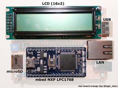
'StarBoard Orange' is a base board for mbed NXP LPC1768 designed by @logic_star.
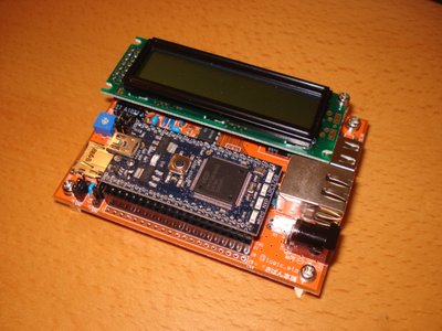
The board includes
- microSD card connector
- USB (Host side)
- LAN(RJ-45)
- LCD
You can use these features for various applications.
In this document, we will explain how to solder these parts.
What you need to prepare
- StarBoard Orange
- Components (BOM is available later in this document.)
- mbed NXP LPC1768
StarBoard Orange
You can purchase StarBoard Orange and the cecessary components from kiban-honpo in Japan.
You can buy it if you live in Japan. If you don't ... Please ask to them or search in Amazon web store.

Bill of materials
Here is the BOM, as of 2010/09/14.
This component list may not latest version. Please see latest version of it from here : Latest component list
Soldering
Soldering surface mounted component (CN2)
The first part to solder is a surface mounted component, CN2.
You should solder it first because the pads of the component are very small.
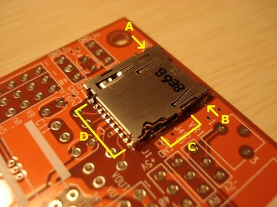
Put on the microSD connector to the board, and solder at 'A'. This is temporary joint.
Check the position, and solder at 'B'.
After the soldering of these 2 points, check the position of 2 pads around C and 10 pads around D.
And then solder pads on 'C' and 'D' if the position is OK.
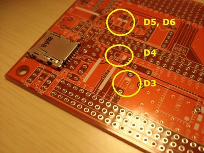
Soldering polarized components (D3, D4, D5, D6)
Lets solder polarized components.
You may solder polarized components first to make later soldering easier.
The diodes are installed here.(D3, D4, D5, D6)
The casode sides of the diodes are marked by white lines on the silk of the PCB.
This is matched to the sign of the diode.
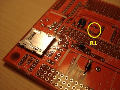
Soldering non-polarized components (R1, C1, C2, C3, C4, C5, C6, C8, C9, C13
Lets solder non-polarized components.
Start with a resistor. (R1)
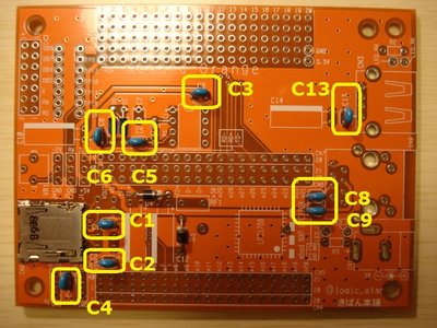
Solder 0.1uF capacitors (C1, C2, C3, C4, C5, C6, C8, C9)
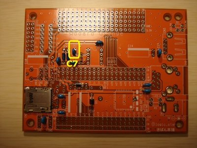
Solder a 1000pF capacitor (C7)
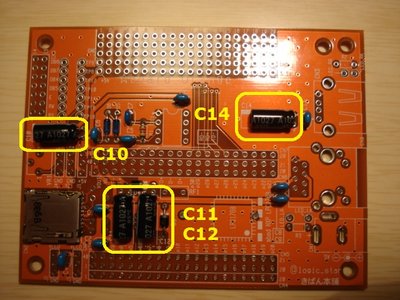
Soldering polarized components (C10, C11, C12, C14)
Solder polarized capacitors. (C10, C11, C12, C14)
The minus sides of the polarized capacitors are marked by white lines on the silk of the PCB.
This is matched to the sign of the capacitor.
BreakTime
Have a break! 
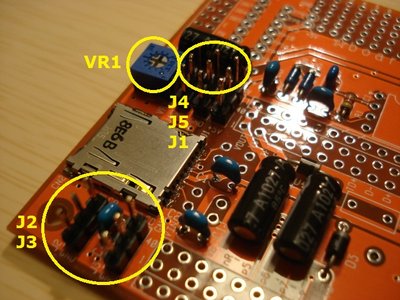
A variable resistor and jumpers (VR1, J1, J2, J3, J4, J5)
Solder a variable resistor and jumpers. (VR1, J1, J2, J3, J4, J5)
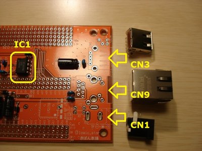
IC and connectors (IC1, CN1, CN3, CN9)
Solder an IC. (IC1)
Check the polarity by the silk on the PCB.
Solder connectors. (CN1, CN3, CN9)
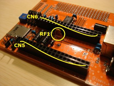
Connectors and a resettable fuse (CN5, CN6, CN8, RF1)
Solder connectors for mbed. (CN5, CN6)
Solder resettable fuse. (RF1)
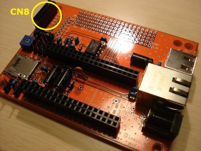
Solder a connector for LCD module. (CN8)
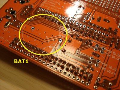
Misc. (BAT1)
Solder a battery holder. (BAT1)
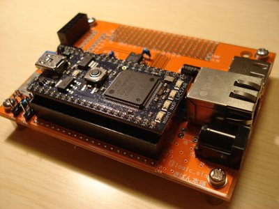
The last part
Put on mbed.
Check a space between mbed and RF1.
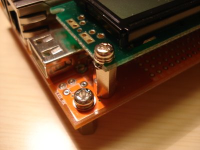
Put on a LCD module to the board with a spacer.
The height of the spacer is 11mm.

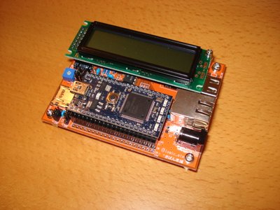
Here is the result.
It's done!
It's the your mbed kit!
Setup of the jumpers
The board have 5 jumpers.
To complete work, setup jumpers.
| Jumper | Description | Upper side | Lower side |
| J1 | Choose a voltage of a LCD module. | +3.3V | +5V |
| J2 | Choose a function of a pin #2 of LCD module. |
Give a voltage you selected in J1. | Give a 0[V]. |
| J3 | Choose a function of a pin #1 of LCD module. | Give a voltage you selected in J1. | Give a 0[V]. |
| J4 | Choose a reference volage for contrast of a LCD module. | Give a -2[V]. | Give a 0[V]. |
| J5 | Choose a connection for R/W- of a LCD module. | Connect R/W- to mbed. | Connect R/W- to 0[V]. |
References
Basic information
- StarBoard Orange: mbed評価用ベースボード(in Japanese)
- 'mbed' -Rapid Prototyping forNXP LPC Microcontrollers in Minutes
- StarBoard Orange : "Soldering step by step"
- StarBoard Orange : "Expandability of StarBoard"
Application examples
- StarBoard Orange : "Application example No.1 : Enjoy mbed world with just one sensor!"
- StarBoard Orange : "Application example No.2 : Add many buttons to your application with IR remote!"
- StarBoard Orange : "Application example No.3 : Drive a CHORO Q with wii nunchuck!"
Update history
| Version | Date | Description |
| 1.0.0 | 2010/08/06 | First version. |
| 1.0.1 | 2010/08/14 | Added application examples to references. |
| 1.0.2 | 2010/08/15 | Changed DC power jack. |
| 1.0.3 | 2010/08/16 |
Fixed name of StarBoard Orange |
| 1.0.4 | 2010/08/23 | Added a link to latest component list. |
| 1.0.5 | 2010/08/23 | Updated spacer and screw. |
| 1.0.6 | 2010/09/09 | Updated english words. |
| 1.0.7 | 2010/09/10 | Updated links of application examples. |
| 1.0.8 | 2010/09/15 | Updated links of web sites. |
0 comments
You need to log in to post a comment
StarBoard Orange : "Soldering step by step"
'StarBoard Orange' is a base board for mbed NXP LPC1768 designed by @logic_star.
Page owner:  Shinichiro Nakamura
Created 05 Aug 2010.
Last updated 15 Sep 2010