ScottROV
For my final year Individual Project on the Electronic Engineering degree course I am doing at the University of Westminster, I decided to build an underwater robot (more commonly known as an ROV - remotely operated vehicle).
The general idea is to have a vehicle that is controlled by an out-of-the-water operator who can see where the vehicle is heading via a video camera link. Unfortunately this was deemed not quite complicated enough so I added a self-levelling control system to the specification.
The basic design I came up with has:
- PVC frame and water-proof enclosure
- mbed-based, joystick-controlled operator interface (Top Controller)
- mbed-based motor controller (Bottom Controller)
- 30 m cable connecting the two controllers (known as a tether)
- 7 DC motors fitted with propellers (known as thrusters)
The project has been very challenging and is essentially a success, however at the time of writing, the control system is still not finalised, and the video camera is awaiting replacement. This is a short summary of the project and much greater detail can be found in the project report linked at the bottom.
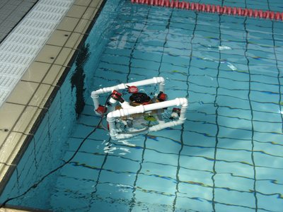
Frame
The PVC frame is made up of 32 mm diameter drainage pipe and some suitable 90 degree elbows and T-junctions. This material is cheap, readily available, and easy to work with.
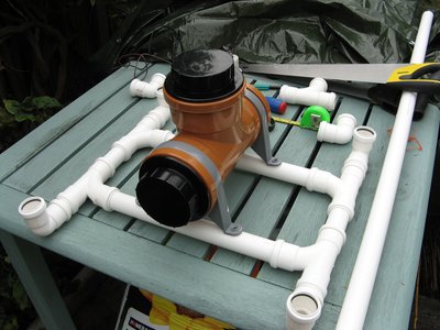
Enclosure
To minimise costs, it was decided to use 110 mm drainage pipe with suitable end-caps for the water-proof enclosure (as shown in the photo above). It was unclear if this would actually work as the fittings are designed to keep water in, not out: the rubber seals are shaped the wrong way. Testing to 5 m has so far been successful but I am not yet fully confident of taking it much deeper without more testing. A window has been machined into one of the end-caps for the video camera to look out from, and an 18-pole connector fitted to allow signals (to the motors and to and from the top controller) to pass in and out of the enclosure.
Thrusters
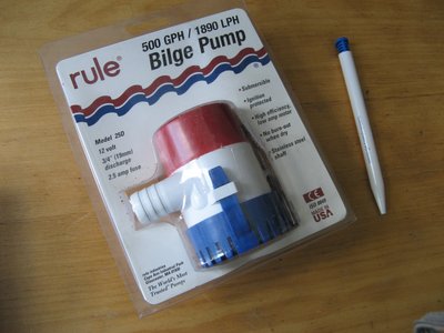
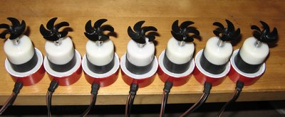
Seven thrusters are employed for positioning: four for horizontal movement, and three for vertical movement. For a basic ROV, it is possible to get away with using fewer (four is probably the minimum) but with the self-levelling system I ended up with seven. They are constructed by modifying bilge pumps. These are pre-sealed and designed to be submerged. The covers were machined off, the impeller removed, and then the propellers were added. Before:
After:
Top Controller
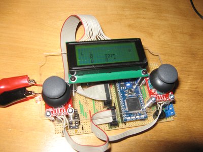
The Top Controller is driven by an mbed connected to an LCD screen, four switches, six LED's, two analog joysticks, a temperature sensor, a piezo buzzer, and an RS232 driver IC.
Bottom Controller
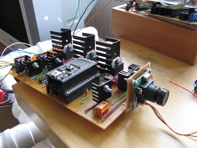
The Bottom Controller is also driven by an mbed connected to five MOSFET's, three H-bridge IC's, a temperature sensor, a leak detector, an RS232 driver IC, and an IMU board. This IMU board is fitted with a 3-axis accelerometer, a 3-axis gyroscope, a 3-axis magnetometer, and a micro-SD card socket. Two axes of the accelerometer are used for the tilt sensing, and the micro-SD card is used for data logging.
Tether
The Top Controller is connected to the Bottom Controller via a 30 m ethernet cable. This cable is used to transmit operational instructions to the ROV from the operator, and receive sensor data and video images. Only two of the four twisted pairs inside the ethernet cable are actually used: two wires for serial data, one wire for video, and one wire for ground.
Control System
The self-levelling control system operates on two axes: pitch and roll. The pitch axis is corrected using the vertical rear thruster, while the roll axis is corrected by the left and right vertical thrusters working in unison. The control system uses a PID controller (from the mbed library) but it still needs to be "tuned" for optimal performance.
Results
Operationally it works fine. It moves around freely in all directions and does exactly as was envisaged:
Summary
This project provided many challenges but they can mostly be summarised as:
Water-proofing, on a limited budget, with inadequate tools is hard.
... if only I had a CNC mill and laser cutter.
Having said that, there were many positives to come out of it: it will come as no surprise to most of you, but the ease-of-use that comes with the mbed development system, along with all the libraries available, made the whole process so much easier than it might otherwise have been. So thank you to everyone that contributes to this community.
I would like to take this opportunity to thank the mbed team, the staff and students at the University of Westminster, the forum contributors at homebuiltrovs.com, and Tim Marvin for his IMU.
Further details can be found in the project report: project report.
8 comments on ScottROV:
Please log in to post comments.


Very Cool Project!!!
It's an awesome robot, how you implemented control? PID? Fuzzy? congratulations this looks very cool.
P.S. This link is down http://mbed.org/users/scotto/notebook/scottrov/%5B%5B/media/uploads/scotto/project_report.pdf/