LM75B temperature sensor interface
Here are two study projects to get data from I2C device(s).
What is this?
A sample code to get temperature values from two LM75B devices on same I2C bus.
The temperature read out will be shown on serial terminal on the PC screen.
Code:
LM75B_test:
http://mbed.org/users/okano/programs/60d3e
This was written like C-language style.
TempSensor_LM75B
http://mbed.org/users/okano/programs/5yg0k
LM75B_test2: ** old version has been removed
http://mbed.org/users/okano/programs/5z9zq
This was written in C++ style. The code is very simple in main() function. The temperature sensors are handled as each instances like mbed's AnalogIn interface.
This project requires two header files which defines classes.
"I2cBusDevice.h" is a generic class for I2C devices.
"TempSensor_L75B.h" is a derived class of I2cBusDevice.
Note:
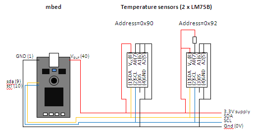
Both of those programs can drive two LM75B devices. These two sensors should have different I2C address setting using its address pins (LM75B's A0 to A2 (pins 5 to 7)).
One LM75B should have all those pins tied to GND, and the other should have the pin A0(pin7) pulled-up.
From the software, those devices can be accessed by I2C addresses "0x90" and "0x92".
It will not be as "0x90" and "0x91" since the address has 7 bit only and stuffed to left. So the "A0" setting become second bit from LSB.
The LSB does not care because it will be set by I2C libraly when it transfer the data for read and write.
On these programs, expecting to use the pins 9 and 10 for I2C bus and these pins should be pulled-up properly.
Reference:
LM75B datasheet
www.nxp.com/pip/LM75B_2.html
これは?
I2C上に接続された2個の温度センサLM75Bから温度データを受け取るサンプルコードです.
温度の情報はUSBシリアルで接続されたPC上のターミナルに表示されます.
コード
上記「Code」の項のリンクを参照.「LM75B_test」はC言語ライクな記述,「TempSensor_L75B」はC++的な記述を取り入れ,main関数内をシンプルにしました.温度センサは,ちょうどmbedのAnalogInのようなインスタンスとして扱われます.
このプロジェクト(プログラム)には2つのヘッダファイルを用います.
「I2cBusDevice.h」はI2Cデバイスのベースクラスとして,「TempSensor_L75B.h」はそこからの派生クラスとして使われます.
注意
この二つのサンプルプログラムは(同一I2Cバス上の)2個の温度センサからデータを受けるようにしてあります.これを行うため各温度センサには,そのチップの5ピン~7ピン(A2..A0)を使って,別のI2Cバス・アドレスを設定しておきます.
一方のLM75Bは,これらのすべてのピンをGNDに接続,もう一方はピン5(A0)だけをプルアップしておきます.
ソフトウェアからそれぞれのデバイスへのアクセスはI2Cバス・アドレス0x90と0x92で行います.
アクセスするアドレスは0x90と0x91とはなりません.デバイスで設定するA0はI2Cアドレスを設定する変数の最下位ビット(LSB)とはならず,下から2番目のビットとなるためです.
アドレス変数のLSBは「Don't care」となります.I2Cライブラリがリード/ライトの転送方向に合わせて上書きするためです.
このサンプルプログラムではI2Cバスにmbedの9ピンと10ピンを使います.これらのピンは適切にプルアップされてなくてはなりません.
参考
上記「Reference」の項を参照
0 comments
You need to log in to post a comment
LM75B temperature sensor interface
A sample code for temperature sensor LM75B
Page owner:  Tedd OKANO
Created 21 Jan 2010.
Last updated 27 Jan 2010