ERIC the RoboDog
I recently completed my MSc thesis in Robotics at the University of Essex. This culmenated in a walking robot that used two mbeds at its heart. This page is not aimed at explaining every aspect of the project, rather it highlights of some of the challenges faced and how they were overcome.
The birth of ERIC
ERIC (an acryum of Embedded Robotic Interactive Canine - every robot needs a snappy name...) is a autonomous walking robot quadruped born from a necessity to complete a project that would hopefully get me a good mark at university!
I wanted to do something using mbed as I had used it before (my BEng degree project used mbed to control a motor, the result of which can be seen here), but I wanted to do something with a bit more 'wow' factor. I've spent several years showing my wife my various projects only for her to shrug here shoulders and say "that's nice dear". I was determine that this project would pass the 'wife test' and impress her.
I felt that a robotics degree project should produce a robot, and originally thought of doing a robot spider or hex-a-pod. I then saw how much servos cost and decided to reduce the leg count somewhat! So what has four legs - a dog, perfect a robot dog. What do dogs do? Well they obey their masters commands and fetch balls. Can I mimic those behaviours?
I knew I was doing a computer vision module as part of the MSc so I though I might be able to something vision related and I figured that the rest would fall in place as I went along - after all I had two years to build it.
The early days
I started developing the physical and kinematics side of things. This was mainly because I wouldn't do the computer vision module until year two of the course and would need a physical platform to develop on. I also started a logbook page for ERIC so I could record aspects of the project for when I needed to finally write the report.
Before I done anything else I started testing some servos. I knew that I would need to control a lot of them and while I could use the servo library (documented in this cookbook entry) this would maybe not be suitable. This is because most servos are controlled via PWM, and the mbed only had six of these outputs available. I started to look for other solutions and found inspiration from Chris Styles' AX-12+ notebook page. These would be perfect as they are controlled by serial commands and can be daisy chained together on a single bus - so in theory I could control up to 254 of them.
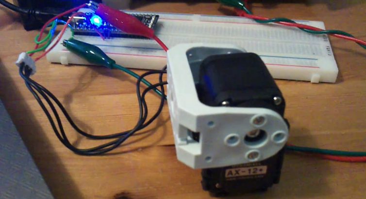
I got hold of some and soon got the 'hello world' program working. More details were added to my logbook here and I was up and running. The next thing I though about was how I was actually going to control the legs and make ERIC walk. Other robots I had read about used something similar to stop motion animation. This is done my recording the servo positions of the robot in a standing position, move a leg forward a bit by hand, record servo positions, repeat, repeat again, and again, etc. The robot then 'walks' by 'playing' these poses back one after another.
I wanted a slightly different approach which allowed me to control the position of any foot at any moment in time. I could then describe the foot motion mathematically in terms of time and ERIC would simply walk forward. An example of this type of application (warning contains maths...) would be if y_position = cos(time) and x_position = sin(time) then foot position would trace around the perimeter of a circle with a radius of 1 going round the entire perimeter every 2 pi seconds. I'm a big fan of testing and prototyping stuff so I tested the theory by knocked up a quick rig that moved a simple leg mock up under mbed control.
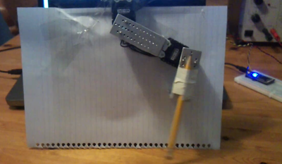
Before I could go any further I needed to think about what kind of movement I would need to do. As I was going to model the robot on a similar physiology to a small dog, I would definitely need a knee joint and a hip joint. I decided to add a second degree of freedom (DOF) to the hip joint allowing the leg to move outwards. I thought this type of movement would be vital for rotation and turning.
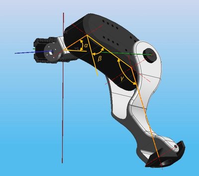
The addition of this new joint meant I needed to be able to calculate the servo angle solutions to a mathematical expression in 3 dimensions, not 2. The result was an inverse kinematics engine that would do just that - returning the correct hip and knee servo angles to move the foot to the desired position. The final IK engine could work out all the angles for all in legs in under half a millisecond and all the legs could be moved to a new position several hundred times a second - much better than the stop motion approach.
A look through the development page shows just how much maths the mbed is processing - and not just simple stuff, trigonometry, square roots, floating point division, all are crunched by the mbed's Cortex M3 with impressive ease. As part of my written thesis I discussed how powerful the mbed processor actually was. My conclusion, something on part with the first Pentium processors in the early 1990's. This is seriously impressive when you consider that there is no heatsink, the memory is held onboard, and it is much smaller. Moore's Law in action...
Early life
With a basic plan of attack I now had everything I needed to control a walking robot, all I needed was a body. Once I had settled on using the AX-12 servos I could start to package legs around the servos and design the over leg. I needed to retain maximum movement of the knee joint and to keep the torque requirements to a minimum I positioned the servos as close together as possible. The final configuration utilised 6 servos to form the hind legs.
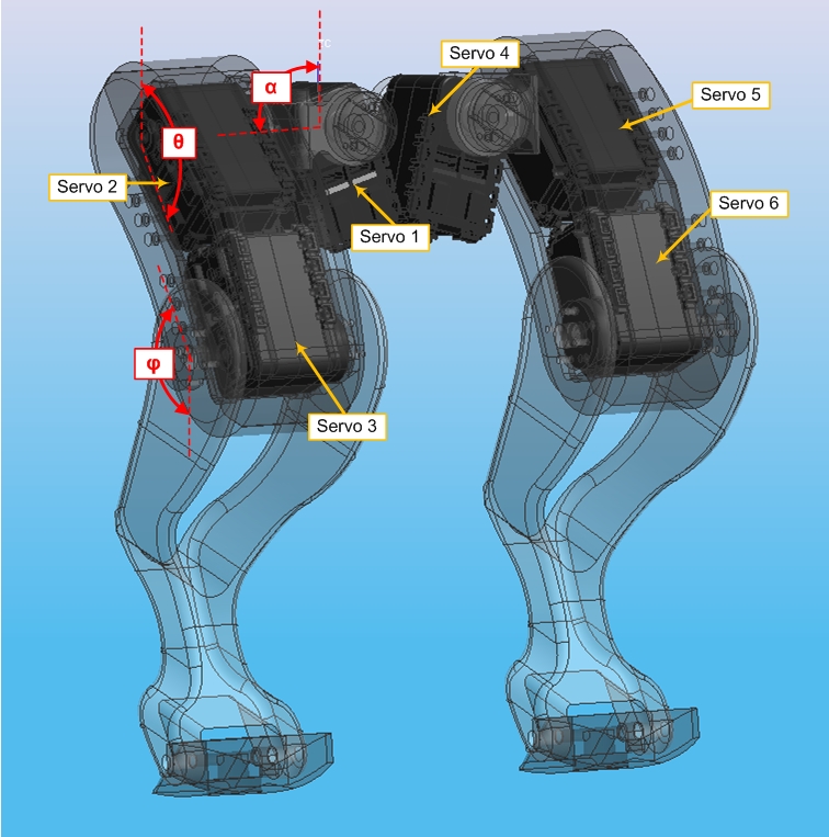
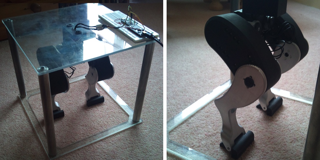
At this point I could start to cut metal. I was able to make the components directly from the CAD models either by using CAM on a 3-axis milling machine or by using a 3D printer. Here are some pictures of the legs at various stages of manufacture...
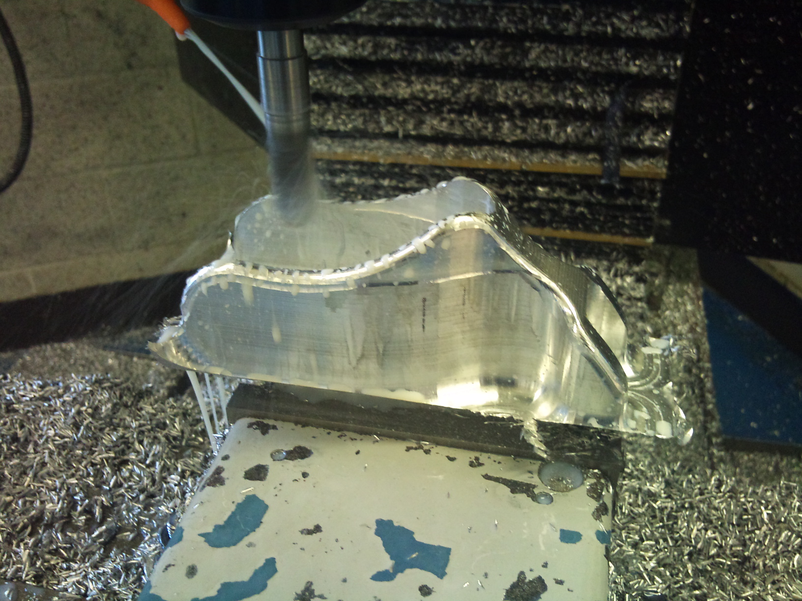
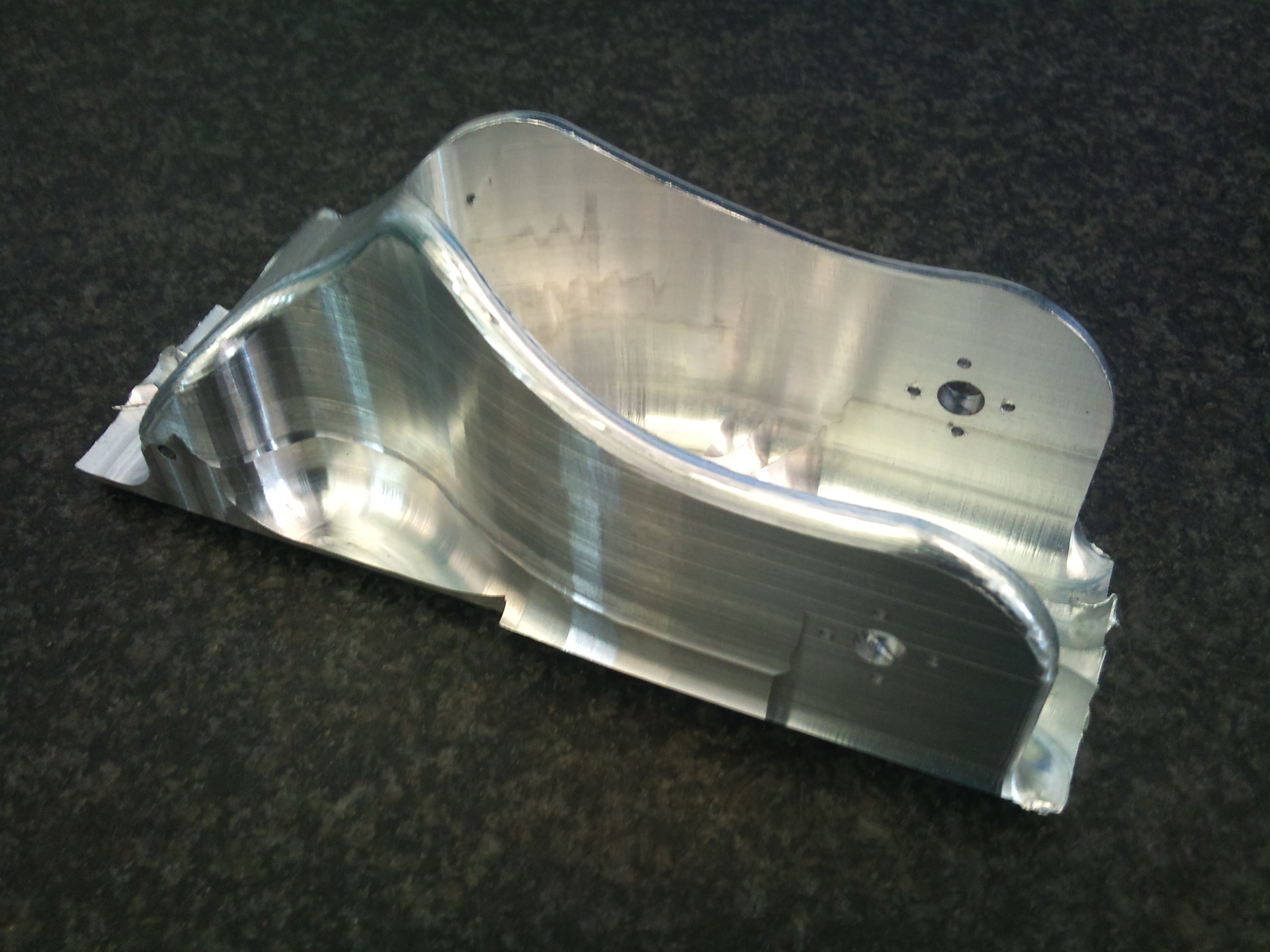
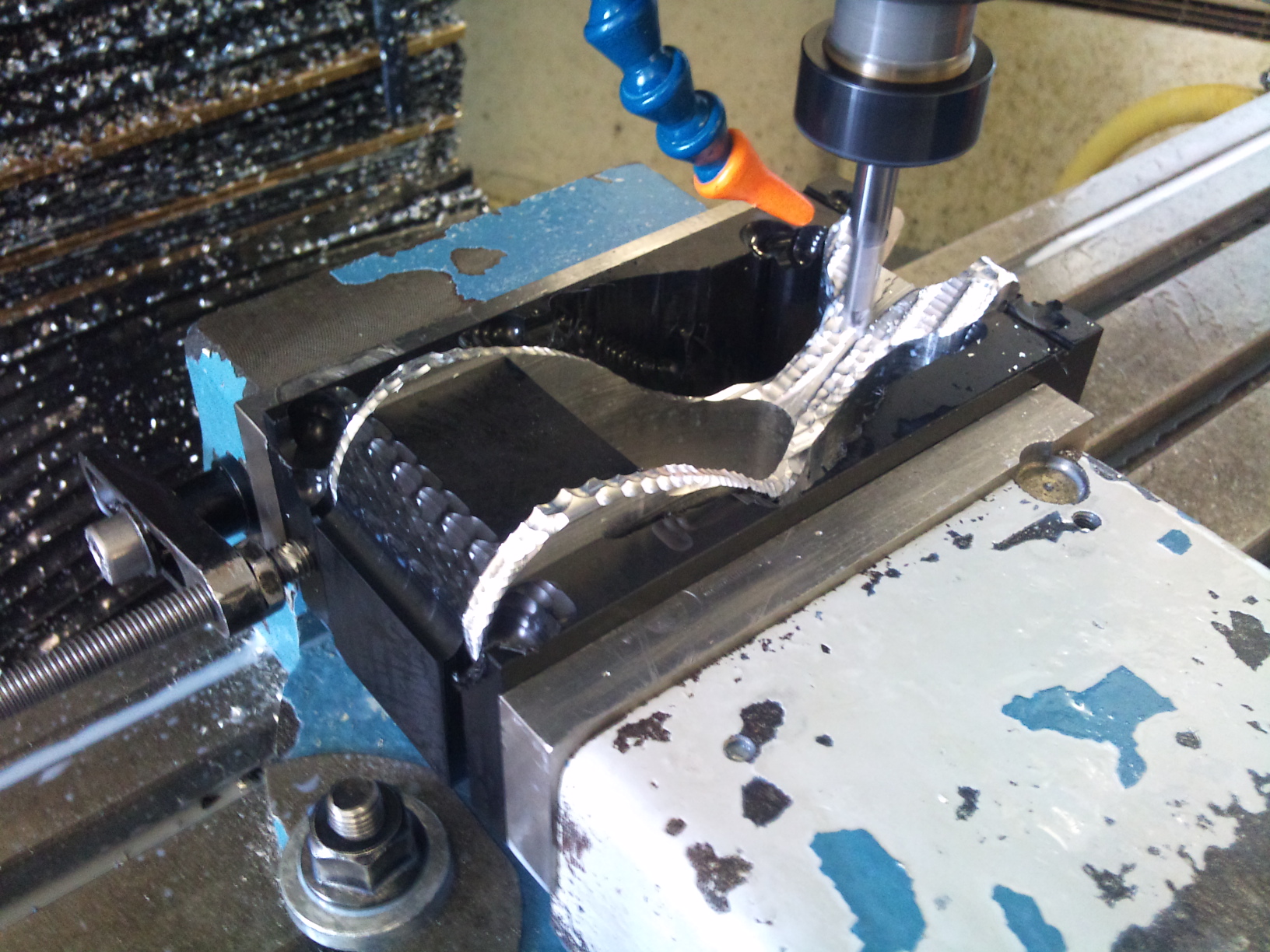
Add a few bolts and and I had a set of assembled hind legs that I could start to develop code on.
Teenage years
Before I made the front legs I wanted to prove I could control the 6 hind leg servos and get them to walk. This would prove the IK engine, the servo control and the mechanics thus far. I got both legs moving in the same pattern (the foot position moving in an ellipse) and phase shifted the two legs by 180° to make them anti-phase. There was no way this was going to balance by itself so I added some string to the rig so I could keep it upright. The results can be seen on this video...
I was quite happy with this as it proved not only the concept but also that the servos were powerful enough to move the body. The next stage was to make the front legs. Some machining time later and I had four legs - now I just needed to make them walk. For this I still used the same repeating mathematical elliptical foot motion but phase shifted each leg by 90° instead of 180°. This meant I was free to try out different footfall patterns (gaits) and see which ones work and which don't. Again inspired by nature I used the same gait as a dog uses when it walks.
To begin with I just moved the legs with no body weight shift - this didn't work. Later I settled on moving the COG over the standing legs before lifting the moving leg off the floor. The two approaches are presented below.
I was now in the position where ERIC could walk over the ball if he knew where it was, be first he would need to find it! To do this I would need a camera...
Coming of age
ERIC needed a head within which to mount the camera. This was designed and again 3D printed. The head only weighs around 250 grams but as it protrudes quite a long way from the body, and raises ERIC's COG, it caused some instability and balance problems when walking. This was counterbalanced with the introduction of a tail with a 150 gram stainless steel mass on the end! This is also the reason for the lightning holes in ERIC's legs - I had to put him on a diet. All in I took nearly 750 grams of mass from ERIC which improved his stability greatly.
A PCB was made (including black solder resist) that held both mbeds and allowed the camera, battery and servos to all be interconnected into a single neat system. The PCB is contoured to fit neatly on his back. ERIC's eyes are also small PCBs that each contain 6 blue LEDs that are connected to the servo mbed. They are controlled using the BusOut interface which updates using a Ticker object to create the famous Cylon effect - this does absolutely nothing except look cool! ERIC is powered by a 1000mA LiPo battery which allows for 10 - 15 minutes of 'walkies'. A diagram that outlines ERIC overall system can be found here
The camera used again came with help from the mbed community, specifically fuyuno sakura who had written a library for the OV7670 embedded camera module. This module uses a parallel data interface which means it is inherently faster than the serial modules I had previous used. This was a good thing as I had set the goal of taking and analysing a picture to find the ball in under 1 second.
I have had a few questions on how I done the computer vision and have decided to start a notebook page that goes into the subject in a little more detail. In summary the process is outlined below:
- First ERIC has to take a photo - this is a RGB565 format 160*120 pixel image
- Next ERIC saves the pixel data into his memory banks - there is enough memory on the mbed to save a single image (38400 bytes)
- ERIC then converts this image from colour to grayscale
- The next stage is to blur the image - this reduces any noise that may have got into the image when it was taken
- ERIC then performs a Sobel transform on the image. This is a simple 3*3 mask (a pair of masks actually) that are passed over every pixel. The mask enhances edge pixels making them appear white and reduces homogeneous regions making them appear black.
- ERIC then selects a grid of candidate points in the picture. At each candidate point ERIC tests pixels in the surrounding pixels to see if they are edge pixels. ERIC keeps increasing the search radius until he finds 5 edge pixels.
- ERIC takes the 5 edge pixels and groups them in sets of three - this results in 10 sets (1,2,3; 1,2,4; 1,2,5; etc).
- For each set ERIC calculates a potential circle whose perimeter lies on all three points.
- ERIC then tests the perimeter pixels on this circle and counts the ratio of edge to non-edge pixels. If the ratio is above a threshold then ERIC has found the ball! Yippee. If not then he continues to go through the sets of points and then through the remaining candidate points. If he draws a blank then there is no ball in the picture.
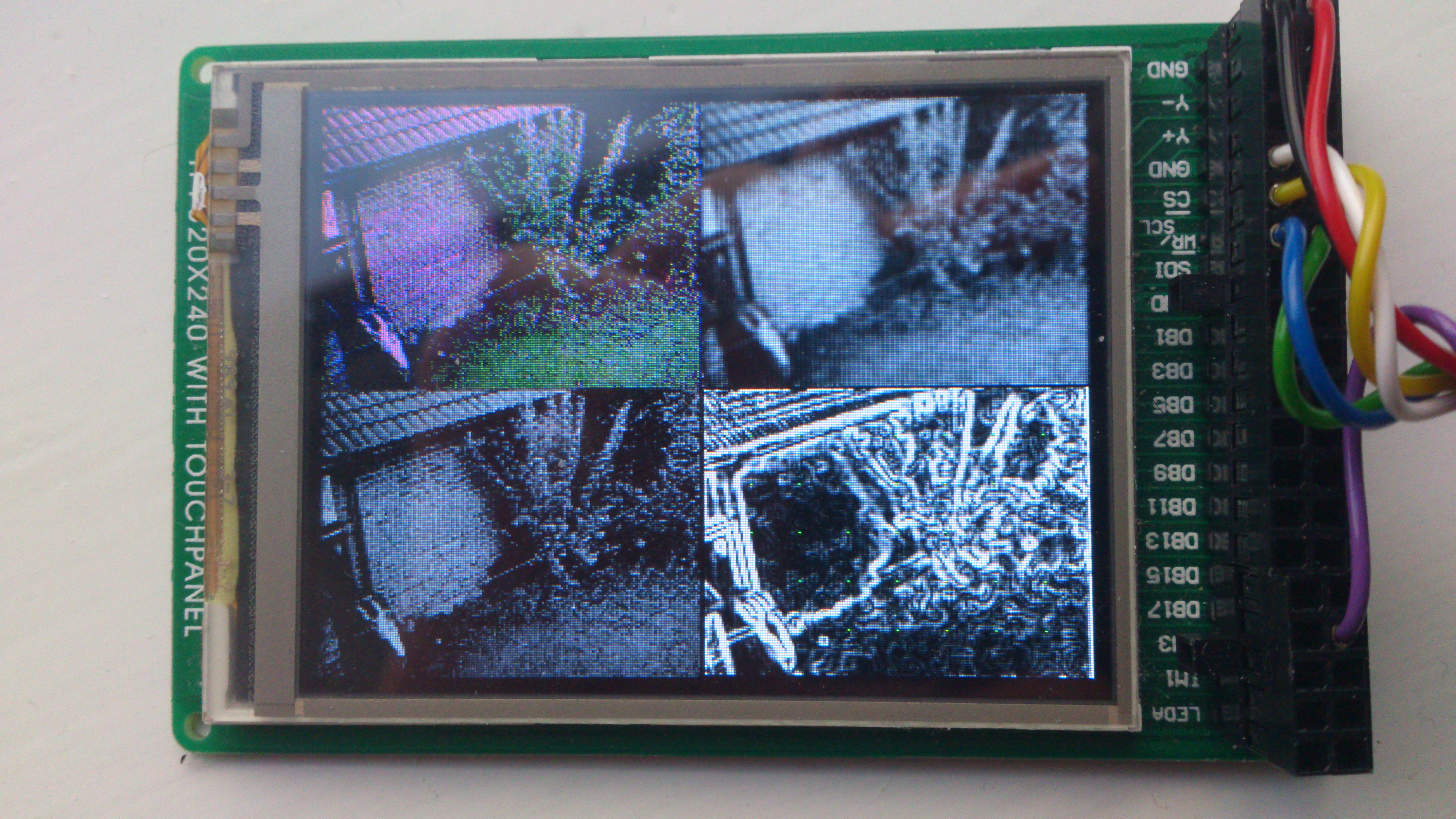
I have timed this process and the entire thing takes around 200 milliseconds depending on the size of the candidate circles derived. Much better than the 1 second I had hoped for. The 'find the ball' algorithm was actually pretty reliable finding the ball in the image >90% of the time so long as there was a good contrast between ball and background. The stages of the algorithm can be seen visually below. The 4 quadrants show colour image (top left), grayscale conversion (bottom left), blur applied (top right) and Sobel transform (bottom right - search grid showing candidate points in green).
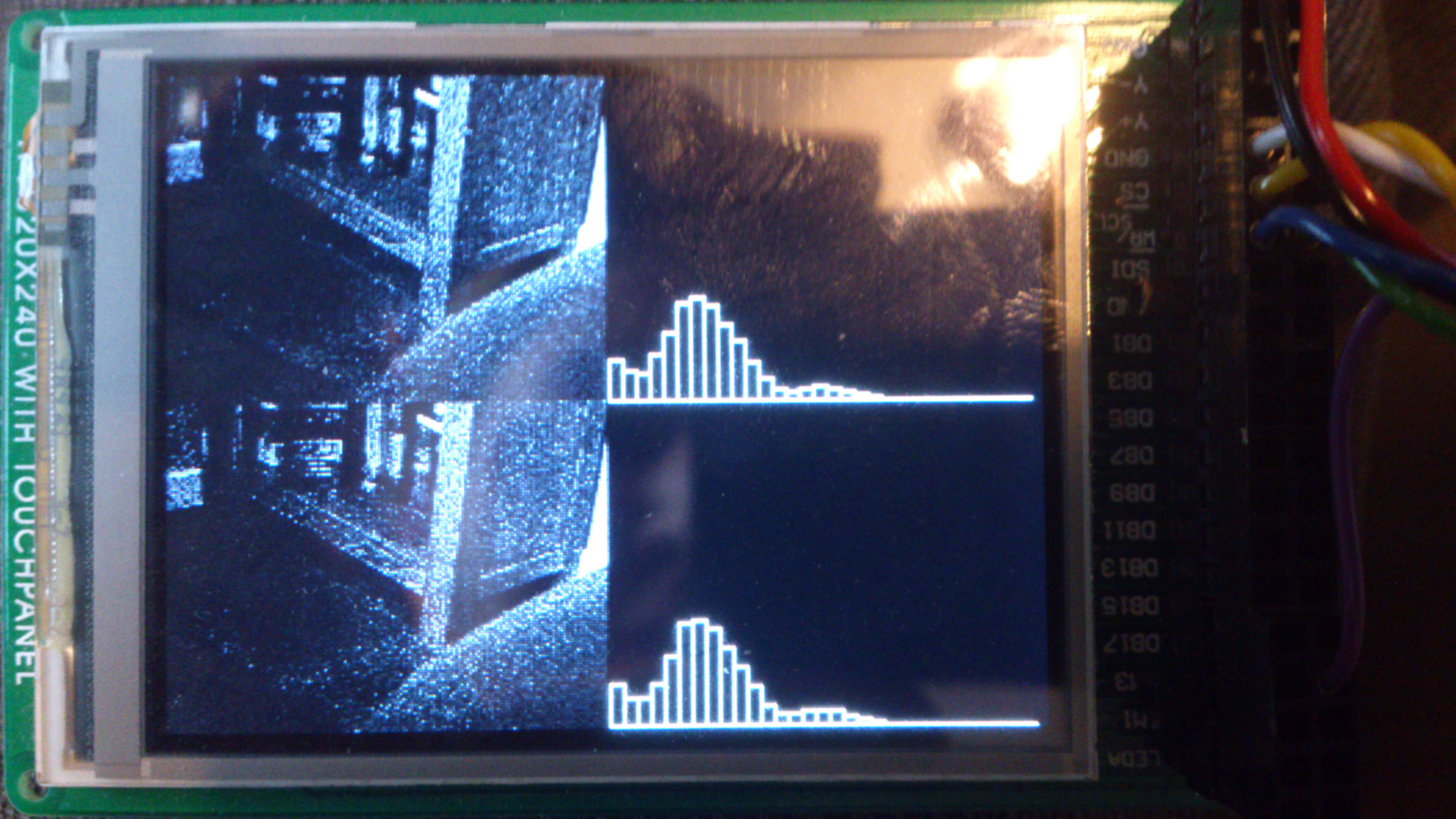
ERIC can also 'guard' an object. This is my favourite ERIC action and is really quite simple. ERIC takes a picture and converts to grayscale. He then creates a histogram with 32 bins. Each pixel is placed in the appropriate bin depending on its value. This leaves a 'fingerprint' for the image. ERIC then takes another photo and repeats the process and creates a second histogram. ERIC then performs a chi-squared test to compare the 2 histograms. If the result of the chi-squared test is above a threshold them ERIC says the image has changed significantly and wakes up. Again this works really quite well - as shown in the video. The 2 images being compared and their respective histograms are shown in the photo below.
The speech recognition that I used to convey verbal commands to ERIC was not so reliable... I used the EasyVR module which had been researched in an excellent notebook page by Jim Hamblen. Using Jim's code as a template I was able to use the EasyVR's built in word lists to send the mbed an ASCII character which instructs ERIC to execute the appropriate movement or action. I don't know if it's my English accent or something else but I found the speech recognition to be quite unreliable, with probably less than 60% accuracy. I should probably invest in a more expensive module?
The future
I don't have any immediate plans for ERIC but may do some improvements in the future. While the mbed performed remarkably well given its limited processing power I would like to do some more advanced computer vision stuff. For this I would have to move away from the mbed and migrate to a Raspberry Pi or a Beagleboard - both of which could run OpenCV. The mbed is still an excellent choice for the AX-12 servo control and maybe could incorporate an IMU to give ERIC a sense of balance. This could lead to the development of some more dynamic walking and trotting gaits, an area which could do with some improvement.
So far ERIC has made it onto the hackaday website, and the YouTube video (below) has over 8000 hits - so he is getting noticed. And more importantly his did pass 'the wife test'.
I have had great fun building ERIC and am proud of how he has turned out. I hope this page gives a good overview of roughly how ERIC works but if you want to know more then add a comment and I'll do my best to respond. I would like to think ERIC might inspire other robot builders to get into the workshop and get creative.
Martin
5 comments on ERIC the RoboDog:
Please log in to post comments.


Never saw before your work it seems to be a lot of hours works and passion for what you want to get. Bravo! But what I would like to recommend you look at this website: http://www.aldebaran-robotics.com/en/
Probably you will get many ideas from there, maybe Raspberry Pi or Beagleboard is good option but that company use Intel Atom CPU. It is obvious that for proper image processing you need to move to something with a lot of RAM and with fast CPU for quick results.
All the best!
Anastasios