LPC812 MAX Experiment: Multi LED
Experiment: Control Multiple LEDs
In this experiment you will learn how to control multiple I/O pins simultaneously. More specifically you will learn how to control six LEDs. This experiment builds on the knowledge you have gained from the previous experiments.
1) Hardware
In this lab you will need:
- 1x breadboard
- 3x push-button
- 9x 330 ohm resistor
- 2x yellow LED
- 2x green LED
- 2x red LED
- cables
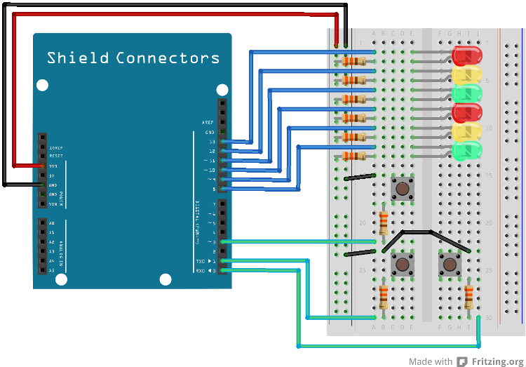
Mount the components on the breadboard and connect the breadboard to the LPC812 as show in the image below.

The pin(s) are specified in the mbed library with the actual pin names as well as some useful aliases:
| Schematic Name | mbed Pin Name | Arduino Shield Alias |
|---|---|---|
| PIO0_0 | P0_0 | D0 |
| PIO0_4 | P0_4 | D1 |
| PIO0_8 | P0_8 | D3 |
| PIO0_17 | P0_17 | D8 |
| PIO0_16 | P0_16 | D9 |
| PIO0_13 | P0_13 | D10 |
| PIO0_14 | P0_14 | D11 |
| PIO0_15 | P0_15 | D12 |
| PIO0_12 | P0_12 | D13 |
1) Description
In this experiment the 6 LEDs shall be controlled in a running-one pattern. First let the running rate be fixed. Use the mbed library's wait function as the time base. The program structure is suggested to be as below. 1) Wait a fixed time, 2) Update the state variable (or counter, which is technically also a state) and 3) set outputs according to state.
Information
Note that only one of the push-buttons is used in this experiment, the other two will be used in the following experiments.
main.cpp
#include "mbed.h"

// Declare variables

int main()
{
    // Set LED start values

    // Enter forever loop
    while(1) {
        // Delay a specified period of time or wait for push-button to be pressed
        ...

        // Update state/counter
        ...

        // Update LEDs according to state/counter
        ...
    }
}
Since there are 6 LEDs is would be suitable to define 6 states or having a counter count between 0-5 (or 1-6, if that makes more sense). The "set outputs according to state" can be discussed in more detail. One method is to first reset all outputs to their inactive state. In our case, that means setting the 6 LED outputs high (which will turn the LEDs off). After that, the state/counter determines which output to set low (turn on one LED). This structure will save code since the resetting to default state is done only once.
Another method, also outlined below, is to set all outputs to correct levels, in each state. This will duplicate much code but the program can possibly be easier to understand and maintain.
// Reset all outputs
...
// Set only the active output
switch(...)
{
    case ...: ... break; //Set only active output
    case ...: ... break; //Set only active output
    case ...: ... break; //Set only active output
    default:
}
or
//Set and reset the outputs
switch(...)
{
    case ...: ... break; //Set only active output and reset all others
    case ...: ... break; //Set only active output and reset all others
    case ...: ... break; //Set only active output and reset all others
    default:
}
It is also possible to experiment with other patterns than the running-one. For example, having 3 LEDs on simultaneously.
When the fixed running rate is working, adjust the program so that a push-button press is advancing the running LEDs instead of time. Simply replace the delay function with a while-loop that waits for a push-button press.
A little twist on above is to add timeout functionality. If the push-button is not pressed for 5 seconds, the running LEDs should be advanced one step. How to implement that?
Tip: sample the push-button at a fixed (known) rate. Count how many times sampling is done. If too many samples without detecting a press, then a timeout has occurred. Define the timeout with a constant (#define ...).
2) Hardware
The same setup is used so no changes are needed.
2) Description
The experiment can only be done partially on the breadboard. The goal is to generalize the previous program. Use two push-buttons for increasing and decreasing the LED running-one speed. Use one more push-button to change the direction direction of the LED running-one pattern and finally use one push-button for start/stopping the LED flashing.
Information
After completing the I2C Experiment you can use the push-button on the LPC812 MAX Board to start/stop the LED flashing.
All-in-all, four push-buttons are needed for this. Only three are available for mounting on a breadboard. Develop the program in steps. First develop the variable speed solution. Then set the speed to a fixed value and continue developing the direction control. Then fix the direction and develop the start/stop control. After these three steps all functionality has been developed. Use the breadboard setup as illustrated in the schematic above.
Solution(s)
Import programlpc812_exp_solution_multi-led
Solutions for the Multi LED experiments for LPC812 MAX
Please log in to post comments.
