RTC Battery Backup Current
The problem
The following thread appeared in the forum, pointing out that the current drawn through the VB pin (RTC battery back up pin) was observed to be a lot higher than expected. Specifically, the report was 175uA, whereas the datasheet for the LPC1768 suggests it should be around 27uA.
The forum thread in question is here :
http://mbed.org/forum/mbed/topic/452/
Confirmation
The first experiment was to make some measurements of my own to confirm what was being seen. I connected the VB pin of my mbed to 3.3v supply via 1k resistor, as the original poster had. This gives me a drop of 1mV per uA, so at the reported 175uA I should be seeing 175mV drop across the resistor - easily enough to measure.
The results came in :
- While powered from USB, Ivb = 10uA
- When unplugged from USB, Ivb = 320uA
This was nearly twice the figures seen by the original poster!
The Cause
Seeing the numbers above triggered a little investigation. The original mbed design was based on the LPC2368, and very little changed on the design when we moved to the LPC1768, as it was essentially a pin for pin replacement.
On the LPC2368, the RTC was powered completely separately. If the RTC was required, Vbat had to be powered, either from the main 3.3v supply, or a battery. Not wanting to run down a battery uneccessarily, a pair of ultra low Vf diodes were put on the board. Expecting a 3.0v coin cell to be used, the arrangement would allow the RTC to be powered from the main 3.3v supply while it was present, and then switch to the 3v battery when the main supply was removed.
The part of the circuit in question is shown below.
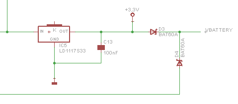
The side effect of this is that when the main power is removed, current will leak through D3 and sink into the rest of the circuit. This isnt enough to power it, but it is enough to notice a significant increase on the expected 27uA.
However, in the newer LPC1768 design this power switching is now built into the MCU itself. If power to the rest of the device is present the RTC will select the main supply to conserve the battery. When the main supply is not present, the RTC will source from the Vbat pin.
Essentially, the diode circuit above is no longer needed.
The Fix
For someone using the mbed NXP LPC1768 and wanting back up the RTC with a coin cell, the easiest fix is to simply remove D3. This will mean there is no path to leak current from the battery back to the main supply rail.
Taking a look at the UNDERSIDE of the PCB, D3 is near the at the bottom, and is the diode closest to the "Pb" symbol, highlighted in bright white.
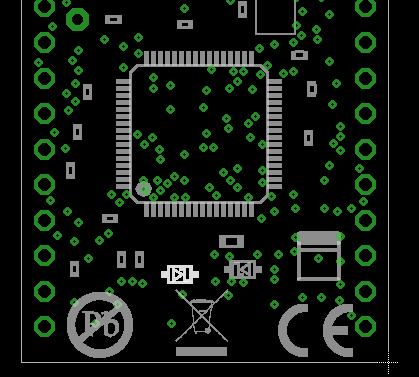 | 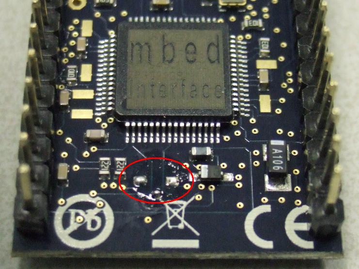 |
| PCB layout view | The actual PCB |
On future build of mbed this diode will not be fitted at the manufacturing stage, For now, it can be easily removed if you are confident with a soldering iron.
If you intend to give this a try, here is the method I used:
- Use a soldering iron with a wide (3mm) tip
- Clean the tip, then tin excessively so there is a little bulge of moulten solder
- While being careful not to touch any other component or via on the pcb, cover the diode with bulge of solder, so that it is touching (and therefore melting) the solder at either end of D3
- Feed in a little more solder if needed, to ensure the solder is melted at both ends
- Pull the iron away from the PCB, the surface tension of the solder should bring the diode away from the PCB with it
- Wipe the solder bulge onto a damp sponge, the diode should be embedded
Verification
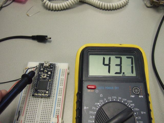
After Sucessfully removing D3, it is time to check the result. Using the same test circuit, a 1k resistor to give 1mV per micrcoamp, we measure the current drawn through VB both with and without the USB power plugged in.
With USB power applied the current draw is down to 20uA, and this goes up to 40uA when USB power is removed. For now this is massive saving, but some further investigation with some higher accuracy measurements is needed.
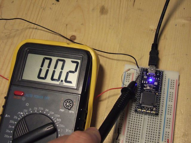 | 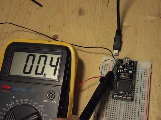 |
| With USB power attached - 20uA | Without USB powerattached - 40uA |
function In the mean time, it is necessary to check the function of the RTC.
I wrote a very simple test program to set the RTC, then print it's value over USB to a terminal in a loop.
#include "mbed.h"

int main() {
    while (1) {
        time_t seconds = time(NULL);
        printf("It is %d seconds since January 1, 1970\n", seconds);
        wait (1.0);
    }
}
With the test program compiled and running, I took the following steps:
- Run the program with no power attached, and ensure that the RTC was actually powered and running by observing the output on Hyperterm.
- Apply 3.v to the Vbat pin, observe that this configuration still works
- Unplug mbed from USB and leave for 10 seconds. In this time RTC should be retained by Vbat
- Plug USB back in, and observe RTC still running, and with a correct value.
Further Verification
The initial results measured above were a good first approximation, but some better measurements were needed. So the tests were repeated using a 10k resistor, giving 0.1uA/mV sensitivity, which led to the following results:
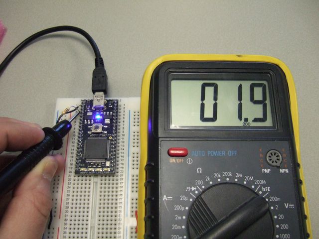 | 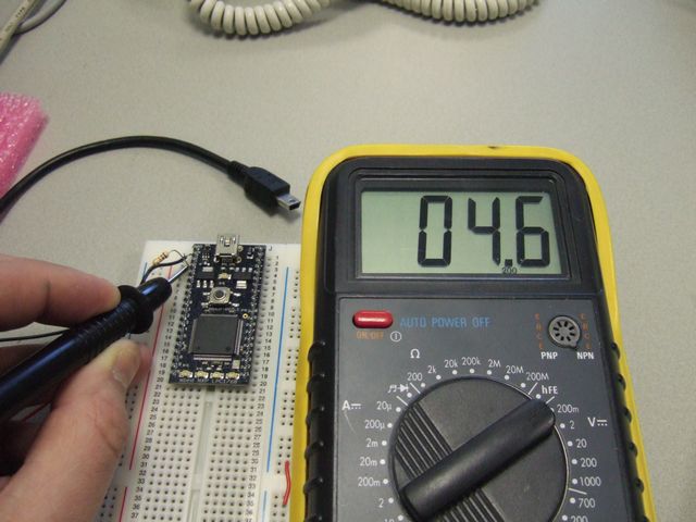 |
| With USB power attached - 1.9uA | Without USB power attached 4.6uA |
Encouraged by this, I repeated again with a 100k resistor, giving 0.01ua/mV
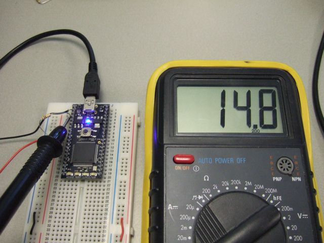 |  |
| With USB power attached - 1.4uA | Without USB power attached 4.3uA |
So it seems that upping the sensitivity of the reading has made us converge on the figures, which are 1.4uA when the LPC1768 is powered, and 4.3uA from the battery. This is still a lot higher than the 0.8uA quoted in the NXP datasheet, but in the abscence of high precision, high sensitivity measuring equipment, the measurements are enough to satisfy us that we can expect a long backup time from a coin cell.
The Other diode
Taking another look at the circuit diagram, you'll spot that a second diode was needed inthe original circuit. With D3 removed, D4 no longer needs to be a diode, but it is doing any harm? The assessment here is that it is not necessary to have a diode there, and in the future, we may be able to fit D4 with a zero ohm link. In the mean time, the effect of the diode is that the Vbat pin of the LPC1768 is being supplied at one diode drop below VB.
The diode used was chosen for its ultra low Vf characteristic, the data sheet can be found at :
Looking at the If vs Vf graph on page 3, at 25^C which I take as room teperature, a forward current of 30uA (3 x 10^-5) we can expect a Vf of less than 100mV, I read it as about 30mV.
So while the diode isn't necessary, it appears from the datasheet that it isnt doing any harm.
The Conclusion
The higher than expected current drain through Vb is due to leakage in a circuit that was neccessary for the LPC2368 mbed, but it no longer needed withthe LPC1768. Future mbed builds will not have this diode fitted, but for those who wish to reduce thier Vb consumption and are competant with a soldering iron, it is a fairly straight forward operation.
11 comments


You need to log in to post a comment
RTC Battery Backup Current
A note page discussing how to reduce the current drawn through VB
Page owner:  Chris Styles
Created 01 Feb 2010.
Last updated 02 Feb 2010
I looked at the drawing and the board and was puzzled for a while before I realized I should look at the bottom of the board. You might want to mention that.