PCA9532 - I2C LED Dimmer
Introduction
This page it intended to show the PCA9532 - what it can do, how it works, how to interface it, and how an API can be built for it.
The PCA9532
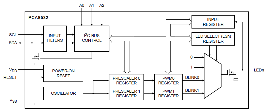
The PCA9532 is an I2C IO expander. it has 16 open drain output pins that are designed to drive LEDs. Each pin can sink 25mA, and can be set to ON, OFF, or blink at one of two programmable rates. The rates are global and have fully programmable period and duty cycle. The achieveable period ranges from 0.6Hz to 152Hz, with duty cycle from 0 to 100% in 256 steps.
 |  |
The PCA9532 device is well documented on the the NXP website that gives links to where to buy it, data sheets as so on
Hello World!
As ever the first thing to do is to establish some kind of communication with the PCA9532. A brief look through the datasheet, suggests that the easiest thing to do is :
- Write 0x00 to Register 0x06 - This switches LED0-3 off
- Write 0x55 to Register 0x06 - This switches LED0-3 on
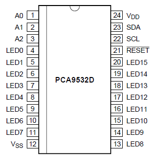
I will do this using the I2C library. The datasheet for this part defines the default address to be 0xC0, and as all the three user defined address bits (A2-0, pins 1-3 on the chip) are all set to zero, this is the final address for this experiment.
#include "mbed.h"

I2C i2c (p28,p27);

int main() {

    char i2c_data[2];

    while (1) {
        // clear LS0 to turn LED0-3 off
        i2c_data[0] = 0x06; // LS0 register
        i2c_data[1] = 0x00; // all off
        i2c.write(0xC0,i2c_data,2);
        wait (0.2);

        // Set LS0 to 0x55 to turn LED0-3 off
        i2c_data[0] = 0x06; // LS0 register
        i2c_data[1] = 0x55; // all on
        i2c.write(0xC0,i2c_data,2);
        wait (0.2);
    }
}
Great! First time around, I got exactly what I was hoping for. The four pins LED0-3 all toggle on and off happily.
Now we're communicating with the PCA9532, we'll look at the registers, addressing, bus transactions, and how to build and API for this.
Addressing
As with many I2C slaves, the address is expressed as an 8 bit byte. The top 4 bits are fixed to a a specific value for the part, the next three bits are controlled by user pins on the physical device (A2-0), this means 8 unique addresses can be set - upto 8 of these on a single I2C bus, and finally the bottom bit is the Read/Write bit. This bottom bit is overwritten as needed in the lmbed library call for read and write.
| 1 | 1 | 0 | 0 | A2 | A1 | A0 | R/nW |
So the top nibble of the address is 0xC, with the bottom nibble being made from the three bit user address and the read/write bit, which is actually a "dont care".
Registers
The functionality of the PCA9532 is controlled by reading and writing the 10 registers of the PCA9532. The registers are pretty stright forward in what they do, and are listed below :
| Address | Mode | Description |
| 0x00 | RO | Input form LED0-3 |
| 0x01 | RO | Input form LED4-7 |
| 0x02 | RW | Frequency Prescaler 0 (period) |
| 0x03 | RW | PWM Register 0 (duty cycle) |
| 0x04 | RW | Frequency Prescaler 1 (period) |
| 0x05 | RW | PWM Register 1 (duty cycle) |
| 0x06 | RW | LS0 - LED Control, LED0-3 |
| 0x07 | RW | LS1 - LED Control, LED4-7 |
| 0x08 | RW | LS2 - LED Control, LED8-11 |
| 0x09 | RW | LS3 - LED Control, LED12-15 |
Reading and Writing
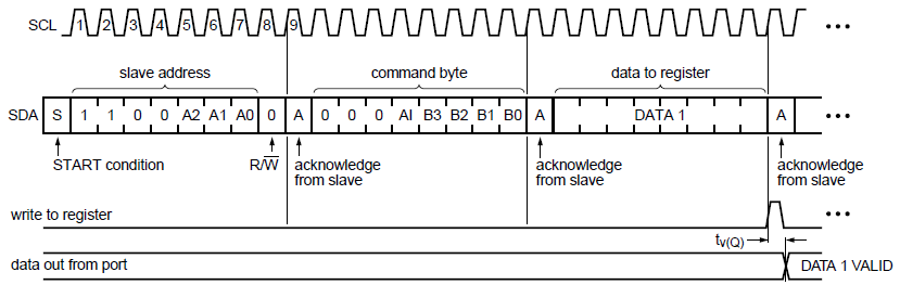
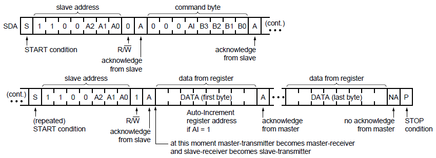
We're already seen that writing to the PCA9532 registers behaves as we'd expect, but reading is slightly different. The PCA9532 uses a control byte, which is essentially just the address. A write is therefore just the control byte followed by the data. A read is slightly different than intially expected. To read from a register, first its address must written to the control byte with an I2C write. The read operation following the write to the control byte returns the address of the register.
Write :
Read :
Building an API
The intention is to build up a C++ class for the PCA9532 so that it can be specifed by pin connection and address, and then controlled in terms of the LED behaviour
Since all of the functionality is controlled through register access, the first step is to build simple methods that give a logical abstraction to the registers, which leads to the following API definition:
class PCA9532 {

    public:
        PCA9532(PinName sda, PinName scl, int addr);

    protected:
        void _write(int reg, int data);
        int _read(int reg);
        int _addr;
        I2C _i2c;
};
The read and write functions are fairly straight forward to define using the bus diagrams above.
void PCA9532::_write(int reg, int data) {
    char args[2];
    args[0] = reg;
    args[1] = data;
    _i2c.write(_addr, args,2);
}

int PCA9532::_read(int reg) {
    char args[2];
    args[0] = reg;
    _i2c.write(_addr, args, 1);
    _i2c.read(_addr, args, 1);
    return(args[0]);
}
Now that we have these in place, all our actual behaviour is a matter of setting registers accordingly.
All of our behaviour can be split into configuring the PWM channels (period, duty cycle) and selecting one of the four modes for each LED (Off,On,Pwm0, Pwm1).
The ways to expose this that seems to make sense is to manipulate one LED, or all at once, e.g.
- Configuring a single LED to a given mode
- Configuring all LEDs to a given mode, via a mask.
Adding in the need to configure PWM channels, the rest of the API looks like this :
int SetLed  (int led, int mode);
int SetMode (int mask, int mode);
int Duty    (int channel, float duty);
int Period  (int channel, float period);
The code to do this has been implemented in the following library:
- PCA9532 - Does not include an mbed library or main.cpp
A hello world program for this library:
- PCA9532_HelloWorld - Full example using the library
This hello world example has a Cheat Sheet for the Embedded Artsist Baseboard
0 comments
You need to log in to post a comment
PCA9532 - I2C LED Dimmer
This is the write up for the PCA9532 I2C LED driver/dimmer from NXP. This part is included on the Embedded Artists Baseboard.
Page owner:  Chris Styles
Created 04 May 2010.
Last updated 07 May 2010