Green's Weather Station
 Adam Green.
0
replies
http,
meters,
server,
sparkfun,
weather,
Web
Adam Green.
0
replies
http,
meters,
server,
sparkfun,
weather,
Web

Import programWeatherStation
Web server based weather station using Sparkfun Weather Meters.
Last commit 25 Feb 2012 by Adam Green
Import libraryWeatherMeters
Library for interfacing to Sparkfun Weather Meters.
Last commit 25 Feb 2012 by Adam Green
Overview
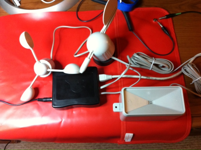
A few years ago, my father and I built an anemometer (wind speed meter) to be placed at my parent's home. I built up the electronics and wrote some firmware for a LPC2148 microcontroller to display the current wind speed on a small LCD display. We had always talked about updating the design to include a larger display and include the ability to log historical wind speed data but it never came to fruition. That particular device stopped working a few months ago so I thought this was a good time to completely replace it with a new design. Since I have been using the mbed device quite a bit over the last year, it was my first choice in microcontrollers for this new design. I knew that the libraries available on the mbed site would make it easy for me to interface with an ethernet network and SD card. I also decided to upgrade the actual sensors to this weather meter set available from Sparkfun. This new design would have no display at all. Instead it would just be connected to the LAN in my parent's home so that any web browser could connect to the new weather station device and be presented with a webpage showing the sensors' latest readings.
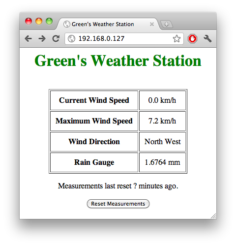
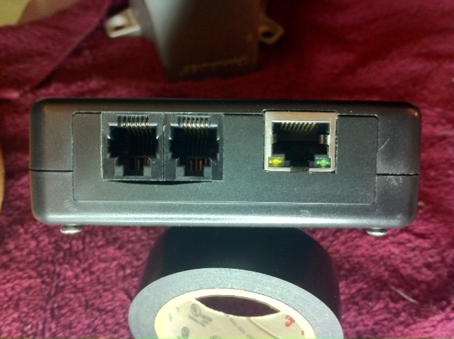
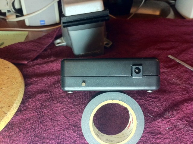
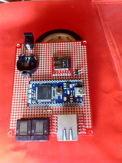
The design I present here doesn't have all of the features that I had wanted to get into the weather station but it does have all of the electronics laid out so that everything I currently have in mind will be easily achievable with firmware updates only. The current firmware is able to present a basic web page containing the current sensor readings. This weather station device contains an ethernet jack so that it can be connected to a network, two RJ11 jacks to which the weather sensors (anemometer, wind vane, and rain gauge) can be connected, and a microSD card slot for retrieval of HTML pages and storage of historical weather sensor data. I placed all of these components into a Sparkfun project case to make the electronics as self-contained and neat as possible. The ethernet port is actually connected to a TRENDnet Wireless N Gaming Adapter TEW-647GA so that it can be bridged onto an existing 802.11n WiFi network.
Bill of Materials
| Description | Sparkfun Link |
|---|---|
| mbed LPC1768 | http://www.sparkfun.com/products/9564 |
| Weather Meters | http://www.sparkfun.com/products/8942 |
| microSD breakout | http://www.sparkfun.com/products/544 |
| 2 x RJ11 connectors | http://www.sparkfun.com/products/132 |
| RJ45 Ethernet MagJack | http://www.sparkfun.com/products/8534 |
| RJ45 Ethernet MagJack Breakout | http://www.sparkfun.com/products/8790 |
| DC Barrel Power Jack | http://www.sparkfun.com/products/119 |
| Wall Adapter Power Supply - 5VDC 1A | http://www.sparkfun.com/products/8269 |
| Coin Cell Holder - 20mm | http://www.sparkfun.com/products/783 |
| CR2032 Lithium Ion 3V 250mAh Coin Cell | http://www.sparkfun.com/products/338 |
| SparkFun Project Case - Black | http://www.sparkfun.com/products/8601 |
| ProtoBoard - Wombat | http://www.sparkfun.com/products/8619 |
| Mini Push Button Switch - Tall | http://www.sparkfun.com/products/8605 |
Wiring
| mbed pin | peripheral |
|---|---|
| GND | DC Barrel Power Jack - GND pin |
| VIN | DC Barrel Power Jack - 5V pin |
| VB | Coin Cell Holder - 3V pin |
| nR | Mini Push Button Switch |
| p5 | microSD breakout - DI pin |
| p6 | microSD breakout - DO pin |
| p7 | microSD breakout - SCK pin |
| p8 | microSD breakout - CS pin |
| p9 | RJ11 connector #2 - pin 4 |
| p10 | RJ11 connector #1 - pin 4 |
| p15 | RJ11 connector #2 - pin 5 |
| TD+ | RJ45 Ethernet MagJack Breakout - pin P1 |
| TD- | RJ45 Ethernet MagJack Breakout - pin P2 |
| RD+ | RJ45 Ethernet MagJack Breakout - pin P7 |
| RD - | RJ45 Ethernet Magjack Breakout - pin P8 |
| VOUT | microSD breakout - VCC pin |
| VOUT | RJ45 Ethernet Magjack Breakout - pins P3 and P6 |
Other connections
- GND pin of Coin Cell Holder should be tied to DC Barrel Power Jack GND.
- Mini Push Button Switch should be wired so that nR is pulled to GND when the button is pressed.
- CD pin of microSD breakout is left unconnected.
- I am numbering the RJ11 pins from left to right looking at the side of the jack where the cable is to be plugged in.
- The following RJ11 connector pins are connected to ground:
- #1 - pin 3
- #2 - pin 2
- #2 - pin 3
- RJ11 connector #2 - pin 5 is connected to p15 on the mbed and also up to VOUT through a 10k pull up resistor.
- GS1 and GS2 pins of RJ45 Ethernet MagJack Breakout should be connected to GND.
- P4 and P5 pins of RJ45 Ethernet MagJack Breakout should be left unconnected.
Photos
Notes
- Data sheet for weather meters is available at http://www.sparkfun.com/datasheets/Sensors/Weather/Weather%20Sensor%20Assembly..pdf
- The current firmware is hardcoded to use a static IP address of 192.168.0.127 so that a user can just open the http://192.168.0.127 link to access the weather station from the local LAN.
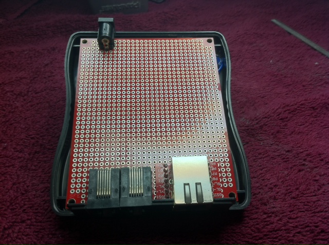
- I used hot glue to attach the two RJ11 connectors to one another so that they could be placed into the ProtoBoard as a single unit.
- I cut out slots in the ProtoBoard to make room for the two RJ11 connectors and the RJ45 Ethernet MagJack Breakout.
- I used a Dremel cut-off wheel for making these slots and a file to fine tune them.
- One slot is large enough for the two RJ11 connectors to fit within and come out flush with the front face of the project case.
- The RJ45 slot is just large enough to allow the solder connections below the RJ11 jack itself to clear the ProtoBoard so that the RJ45 Breakout board can mount level with the ProtoBoard surface itself.
- The slot for the RJ45 jack was also aligned so that the holes in the breakout board would line up with the holes in the ProtoBoard while coming as close to flush as possible with the front surface of the case.
- The RJ11 jacks are hot glued around their edges to keep them in the ProtoBoard.
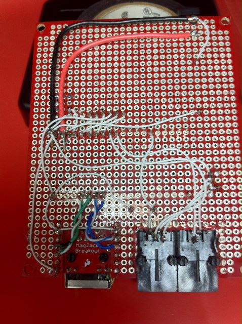
- I used small pieces of stripped 18 AWG solid copper wire to connect the signal pins on the RJ45 Ethernet MagJack Breakout board to the ProtoBoard. I soldered these wires on both the top and bottom and cut off any excess wire left behind.
- I used twisted pair wires salvaged from an unused CAT-5 ethernet cable to make the RD+/RD- and TD+/TD- connections in an attempt to minimize noise on these connections.
- The DC Barrel Power Jack pins don't fit in the stock ProtoBoard holes so I had to drill out larger ones to make it fit. I then hot glued the jack to the ProtoBoard and used large amounts of solder on the pins to provide as much mechanical stability as possible.
- I also removed the third pin on the side of the DC Barrel Power Jack as I didn't need this pin (it is a switch pin which is closed when the power adapter is plugged in.)
- The microSD breakout board is connected to the ProtoBoard through the use of small pieces of 18 AWG solid copper wire.
- A hole was drilled out in the back of the bottom piece of the project case to allow the tall push button to poke out. This button is used for resetting the mbed device.
- The reset button has two wires soldered to it and is hot glued into the bottom of the case. The hole for this button was drilled low enough that the ProtoBoard can clear it when placed on the bottom standoffs.
- The wires from the reset button aren't wired directly to the ProtoBoard. Instead I connected a female 0.1" spaced header to the end of the cable and placed a male connector on the top surface of the ProtoBoard. This allows the board to be completely removed from the case.
- The web server running on the mbed device does require some HTML files to be available on its microSD card. The web content in this archive should be copied to the /webfs directory on the microSD card.
Please log in to post comments.