Important changes to forums and questions
All forums and questions are now archived. To start a new conversation or read the latest updates go to forums.mbed.com.
9 years, 1 month ago.
SSD1289 8 bit multiplexed
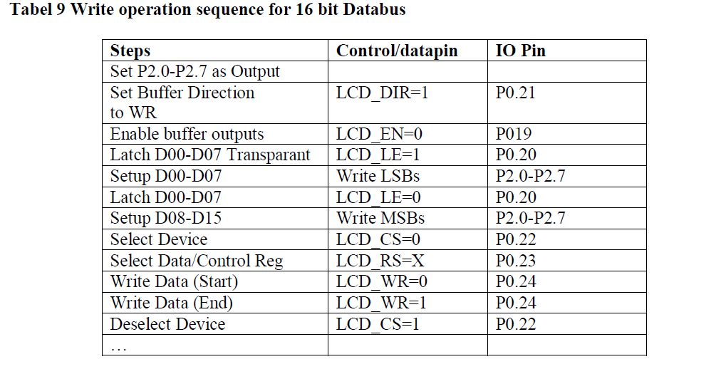
Hi, I'm trying to modified the TFTLCD library for the ssd1289 with 8 bit multiplexed and so far I have changed the WriteCmd and WriteData functions. I'm using for the implementation the Landtiger V2.0 User Manual:

This is my code so far but it isn't working yet :
void SSD1289_LCD::WriteCmd( unsigned short cmd )
{
    _lcd_pin_cs = LOW;
    _lcd_pin_rs = LOW;           // Control Reg
// *_lcd_pin_rd = HIGH;
    _lcd_pin_dir = HIGH;
    _lcd_pin_en = LOW;
    _lcd_port->write(cmd);
    _lcd_pin_le = HIGH;
    _lcd_pin_le = LOW;
    _lcd_port->write(cmd);
//    wait_ms( 25);
    pulseLow( _lcd_pin_wr );
    _lcd_pin_cs = HIGH;
}

void SSD1289_LCD::WriteData( unsigned short data )
{
    _lcd_pin_cs = LOW;
    _lcd_pin_rs = HIGH;       // Select Data
    _lcd_pin_dir = HIGH;
    _lcd_pin_en = LOW;
    _lcd_port->write(data);
    _lcd_pin_le = HIGH;
    _lcd_pin_le = LOW;
    _lcd_port->write(data);
    pulseLow( _lcd_pin_wr );
    _lcd_pin_cs = HIGH;
}
1 Answer
9 years, 1 month ago.
Hi Gregor, it has been some time since I last used the Landtiger board. Never really used the LCD with mbed code. However, the 8/16 bit multiplexer needs to latch the lower 8 bits of the command/data and then setup the upper 8 bits on the portpins. Something like this:
void SSD1289_LCD::WriteCmd( unsigned short cmd )
{
    _lcd_pin_cs = LOW;
    _lcd_pin_rs = LOW;           // Control Reg
// *_lcd_pin_rd = HIGH;
    _lcd_pin_dir = HIGH;
    _lcd_pin_en = LOW;
    _lcd_pin_le = HIGH;
    _lcd_port->write(cmd & 0xFF); // setup LSB
    _lcd_pin_le = LOW;  // latch LSB
    _lcd_port->write((cmd >> 8) & 0xFF); // setup MSB
//    wait_ms( 25);
    pulseLow( _lcd_pin_wr );
    _lcd_pin_cs = HIGH;
}

void SSD1289_LCD::WriteData( unsigned short data )
{
    _lcd_pin_cs = LOW;
    _lcd_pin_rs = HIGH;       // Select Data
    _lcd_pin_dir = HIGH;
    _lcd_pin_en = LOW;
    _lcd_pin_le = HIGH;
    _lcd_port->write(data & 0xFF); //setup LSB
    _lcd_pin_le = LOW;   // latch LSB
    _lcd_port->write((data >> 8 ) & 0xFF); //setup MSB
    pulseLow( _lcd_pin_wr );
    _lcd_pin_cs = HIGH;
}
Thanks for your quick answer. Looks like I still missing something because I 'm getting only the bitpattern from the databus on the LEDs and no changes on the LCD. Do I need the Resetline because I remved it from the original LCD class like this:
LCD( unsigned short width, unsigned short height, PinName CS, PinName RS,  PinName DIR, PinName EN, PinName LE, PinName BL, backlight_t blType, float defaultBacklight );

SSD1289_LCD( PinName CS, PinName RS, PinName WR, PinName DIR, PinName EN, PinName LE, BusOut* DATA_PORT, PinName BL = NC, PinName RD = NC, backlight_t blType = Constant, float defaultBackLightLevel = 1.0 );
I dont have your code, but you have to make sure that the displaycontroller does not stay in reset mode. The Reset pin must be at the correct logic high level to run normally. The lpc1768 pin for reset to the LCD must be configured as DigitalOut and set at 1.
posted by 20 Mar 2015How I'm figuring which pin is for reset because the User Manual says nothing about the Pin number for the reset. Here are my settings for the Pins:
#include "mbed.h"
#include "ssd1289.h"

  // prepare the data bus for writing commands and pixel data
  BusOut dataBus( p26, p25, p24, p23, p22, p21, P2_6, P2_7); // 8 pins
  // create the lcd instance
  SSD1289_LCD lcd( , P0_22, p15, P0_24, P0_21, P0_19, P0_20, &dataBus);// control pins and data bus RESET, CS, RS, WR, DIR, EN, LE, DATA_PORT
  DigitalOut led(P2_0);

  int main()
  {
      // initialize display - place it in standard portrait mode and set background to black and
      //                      foreground to white color.
      led = 1;
      lcd.Initialize();
      lcd.FillScreen(COLOR_GREEN);
      wait(2);
      led = 0;
      // set current font to the smallest 8x12 pixels font.
      lcd.SetFont( &TerminusFont  );
      // print something on the screen
      lcd.Print( "Hello, World!", CENTER, 25 ); // align text to center horizontally and use starndard colors

    while ( 1 )
    {
      wait(0.5);
      led = 1;
      wait(0.5);
      lcd.FillScreen(COLOR_RED);
      led = 0;
    //lcd.Print( "Hello, World!", CENTER, 25 ); // align text to center horizontally and use starndard colors

     }
  }
Hmm, OK, I checked the schematic again. Forget previous remark about the reset pin. Turns out that the LCD is reset by the system reset pin. Same pin as for the LPC1768 itself. So this should be OK.
I am guessing a bit here, but you may want to make sure that the RD pin (P0_25). is also defined and at high level. I noticed that in your declaration the pin is missing and defaults to NC. It should not float but assume a high level when not used.
posted by 20 Mar 2015