Important changes to forums and questions
All forums and questions are now archived. To start a new conversation or read the latest updates go to forums.mbed.com.
9 years, 8 months ago.
mbed for Low Power Charge Control (0.36W)
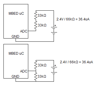
Hello, I am building a solar charge controller for a small, calculator-sized solar panel (3.6V, 100mA) to charge 2 x 1.2v AA NiMH batteries in series. NiMH batteries will be damaged by overcharging, so I wish to detect the voltage level on the batteries and stop charging when the total voltage reaches 2.5V. I have enclosed a picture showing two circuits I have designed. My question is, I would like this voltage detection to draw as little current as possible, so is there a lower limit as to how much current has to flow for the ADC to be able to detect the voltage? I mean can I use a 10M resistor to draw extremely small amount of current?
My other question is do I have to use a voltage divider, as in the bottom circuit, or will the top circuit work?
Regards, Andy

2 Answers
9 years, 8 months ago.
Your top one won't work. how much volt is your mbed going to work at? And are you using the power supply or internal reference as ADC reference (mbed lib uses power supply as default, but you can change that manually). But if you got your mbed running at 3.3V, there is little reason for a voltage divider.
Then it depends on your mbed. The LPC1768 can use a max of 7.5kOhm, so two 15kOhm resistors of a voltage dividers. Also you may not use a large capacitor on the ADC to make a low impedance node (a large capacitor with a series resistor might work though).
I see you have an LPC11u24. In the datasheet the specs for the ADC are. Input impedance is 2.5MOhm. But maximum interface resistance is 40kOhm, so two 80kOhms are allowed. I don't see spec of max capacitance at the ADC node.
Thank you for your reply. I will be powering the mbed from a PC using the USB cable provided. The last time I used the mbed, its ADC displayed a floating output of 0.0-1.0, where 1.0 represented 3.3V. I thought I might not need to use a voltage divider - but what is wrong with the top circuit? How can I fix it so I do not need a voltage divider?
Also, if the input impedance is 2.5M, does that I mean I can simply connect the positive battery terminal straight to the ADC with no external resistor?
posted by 31 Jul 2014If you power it via USB (which is tbh a bit weird if it is for a solar charger, why not charge from USB?), you indeed wil have a nice 3.3V reference. In that case there is no need for resistors and it should just work. A series resistor could be required for capactive reasons (random guess: 10k), but I don't think it will turn out to be required. A voltage divider definately isn't required it it runs from 3.3V.
posted by 31 Jul 2014"Why not charge from USB?" Good question! As part of a university project, I am building a solar charger to charge 2xAA batteries, which will then be used to charge a phone via microUSB cable. I am using a 5V boost converter to boost the battery voltage from 2.4V to 5V in order to do this. The idea is that the phone itself will have a downloadable app which allows it to display variables such as Current/Voltage Output from solar panel, Charge Level of AA batteries, etc, and also prevents overcharging the AA batteries. This app, however, is beyond the scope of the project - I won't be coding it. So for the system demonstration, I will be using the mbed with an LCD screen to carry out the display and charge control functions that I would have expected the phone to do. I hope that answers your question, and thank you for answering mine!
posted by 31 Jul 20149 years, 8 months ago.
I think what you are asking is how much of that suns energy and battery power is going to be absorbed by the ADC input. If you measure this with a meter you will find its about zero at 3.3v input for the 11u24, just tried.
However its sampling at 400KHz and the ADC circuit has very low value capacitors and will lead to approximately 300k impendence so there will be some current drawn from the battery. Allow in the order of a 10uA drain which is not much of a consideration here. Do not connect a series resistor otherwise you will have to calculate the total impendence to work out the ADC read voltage as it will reduce. A 1M series resistor will give an ADC read of 0.9
If you connect your cell directly to the ADC input, when it reaches 2.5v the ADC should read .757 or thereabouts.