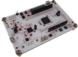
AdBun-M46B
AdBun-M46B development board for Toshiba TMPM46BF10FG MCU.
Overview
The TMPM46BF10FG is ARM® Cortex®-M4F based microcontroller for use in secure systems control, enhanced security features, ideally suited to applications in Internet of Things (IoT) devices, energy management systems, sensor technology, and industrial equipment.
Based on an ARM Cortex-M4F core, with a maximum operating frequency of 120 MHz, the TMPM46BF10FG incorporates 1024 Kbyte of flash memory and 514 Kbyte SRAM required for secure communications control, four types of security circuits for network communications. The MCU also integrates an SLC NAND flash memory controller and 4- and 8-bit error correction circuitry (BCH ECC) that supports memory expansion with 1Gbit to 4Gbit SLC NAND flash memory chips.
To provide additional levels of safety, the IC includes a 16 channel interrupt input and a clock-independent watchdog timer, which operates separately from the system clock, improving the safety of system functions. In the case of a system clock malfunction, the watchdog timer is still capable of detecting errors.
TMPM46B Features
- TMPM46BF10FG in LQFP100 package
- ARM®32-bit Cortex®-M4F CPU, 120 MHz max CPU frequency
- 514KB RAM
- 1024KB Flash
- SSP (3)
- I2C (3)
- UART (4)
- FUART (2)
- TRNG
- PWM (8)
- 12bit ADC (8)
- RTC (1)
- GPIO (71)
AdBun-M46B Feature
- Compatible with a wide range of commercially available shields
- Power option
- USB-UART
- DAP-USB
- DC-Jack
- 4 Push Switch
- 4 LED
- 2 Variable resistor
- Built-in USB drag 'n' drop FLASH programmer
- Prototyping form-factor
RAM size (514Kbytes) means total size of MAIN RAM (512Kbytes) and BACKUP RAM (2Kbytes).
Pin Layout
CN4 Pin Header
The green-framed pins of CN4 are working with 3.3V I/O without level-shifting and connected to the terminal of TMPM46B.

CN9 Pin Header
The green-framed pins of CN9 are working with 3.3V I/O without level-shifting and connected to the terminal of TMPM46B.

CN11 Pin Header
The green-framed pins of CN11 are connected to the terminal of TMPM46B and working with 3.3V I/O without level-shifting, therefore PJ2 to PJ7 can work as Analog IN with maximum voltage of 3.3V.

Arduino Pin Header
When you use Arduino pin, you need to short that connected Arduino pin on CN4, CN9, and CN11. E.g. short: 23-24, 25-26, 27-28 etc: CN11 Arduino pin header of AdBun-M46B Supports 5V I/O only. PJ2 to PJ7 with level-shifting cannot work as Analog IN anymore.


| PWM Pins | UART Pins | I2C Pins | LED Pins | Switch Pins | ||||
|---|---|---|---|---|---|---|---|---|
| PE4 | USBTX = PE5 | SDA = PK2 | LED1 = PF4 | SW1 = PF0 | ||||
| PB6 | USBRX = PE6 | SCL = PK3 | LED2 = PF5 | SW2 = PF1 | ||||
| PH1 | LED3 = PF6 | SW3 = PF2 | ||||||
| PH0 | LED4 = PF7 | SW4 = PF3 | ||||||
| PK1 | ||||||||
| PA7 |
| Arduino I/O Pins | Arduino Analog Pins | Arduino PWM Pins | ||
|---|---|---|---|---|
| D0 = PL1 | A0 = PJ2 | D3 | ||
| D1 = PL2 | A1 = PJ3 | D5 | ||
| D2 = PC0 | A2 = PJ4 | D6 | ||
| D3 = PE3 | A3 = PJ5 | D9 | ||
| D4 = PC1 | A4 = PJ6 | D11 (Depend on S2 setting) | ||
| D5 = PE4 | A5 = PJ7 | D13 (Depend on S2 setting) | ||
| D6 = PH1 | ||||
| D7 = PC2 | ||||
| D8 = PC3 | ||||
| D9 = PH0 | ||||
| D10 = PD0 | ||||
| D11 = PD2 (Depend on S2 setting) | ||||
| D12 = PD1 | ||||
| D13 = PD3 (Depend on S2 setting) | ||||
| D14 = PK2 | ||||
| D15 = PK3 |
| General Purpose Input / Output |
|---|
| PA0, PA1, PA2, PA3, PA4, PA5, PA6, PA7 |
| PB0, PB1, PB2, PB3, PB4, PB5, PB6, PB7 |
| PC0, PC1, PC2, PC3, PC4, PC5 |
| PD0, PD1, PD2, PD3, PD4 |
| PE0, PE1, PE2, PE3, PE4, PE5, PE6, PE7 |
| PF0, PF1, PF2, PF3, PF4, PF5, PF6, PF7 |
| PG0, PG1, PG2, PG3, PG4, PG5, PG6, PG7 |
| PH0, PH1, PH2, PH3 |
| PJ0, PJ1, PJ2, PJ3, PJ4, PJ5, PJ6, PJ7 |
| PK0, PK1, PK2, PK3, PK4 |
| PL0, PL1, PL2, PL3 |
Arduino Pin Header Usage Setting
When using the Arduino's pin header, it is necessary to short-circuit the red line as shown below.


On Board Peripheral Usage Setting
When using LED, Push SW, volume, USB and Dip SW on the AdBun-M46B board, it is necessary to short-circuit the red line as shown below. The purple line is shorted at shipment. If your AdBun-M46B is not shorted purple line, you need to short-circuit purple line.


Technical Reference
Schematics
Data Sheet
Interface Firmware
Please update the interface firmware in the following way when upgrading, or if it has been deleted for some reasons.
- Download Flash programmer that programming tool to program I/F firmware.
When you use the flash programmer, you need to agree "SOFTWARE LICENSE AGREEMENT"
Download Flash Programmer
Download Adbun-M46B Firmware
If you update I/F firmware, before you update the firmware, you need to erase old firmware once.
How to erase I/F firmware
- Short CN14

- Short 5-6 on CN3
- Connect PC to CN15 on Adbun-M46B by mini USB cable

- Start up Flash Programmer
Click FlashProgCM.exe on your PC. - Select [Setup]-[Device]
When you cannot select "Setup device", remove USB cable and select [File]-[Reconnect].
And after procedure 6, connect PC to CN15 by USB cable again. - Select Device "TMPM366FY_EraseALL" and push Apply button on Device tab.
- Select "USB" at Communication tab and push OK button.
- Select [Edit]-[Chip Erase]
Programming procedure is as follow.
9. Remove USB cable
10. Select [File]-[Reconnect] (If not able to select this, it's OK)
11. Select [Setup]-[device]
12. Select Device "TMPM366FY" and push Apply button.
13. Specify firmware that download this site on Object File tab.
14. Reconnect USB cable
15. Push OK button on Setup sheet.
16. Select [Edit]- [Erase/Program]
(If you meet password error, you select "Device is Blank" in Setup Password sheet)
17. Jumper settings
18. Remove jumper on CN14
19. Remove USB cable once
You need to log in to post a discussion
To compile a program for this board using Mbed CLI, use TMPM46B as the target name.
Board Partner
Toshiba
Toshiba Corporation, a Fortune Global 500 company, channels world-class capabilities in advanced electronic and electrical product and systems into three focus business fields: Energy that sustains everyday life, that is cleaner and safer; Infrastructure that sustains quality of life; and Storage that sustains the advanced information society.
 Mbed Enabled
- Baseline
Mbed OS support
- Mbed OS 5.10
- Mbed OS 5.11
- Mbed OS 5.12
- Mbed OS 5.13
- Mbed OS 5.14
- Mbed OS 5.15
- Mbed OS 5.7
- Mbed OS 5.8
- Mbed OS 5.9
- Mbed OS 6.0
- Mbed OS 6.1
- Mbed OS 6.10
- Mbed OS 6.11
- Mbed OS 6.12
- Mbed OS 6.13
- Mbed OS 6.14
- Mbed OS 6.15
- Mbed OS 6.2
- Mbed OS 6.3
- Mbed OS 6.4
- Mbed OS 6.5
- Mbed OS 6.6
- Mbed OS 6.7
- Mbed OS 6.8
- Mbed OS 6.9
Example programs