SDT64B
Low-power, high-performance, Ethernet board enabling direct firmware update
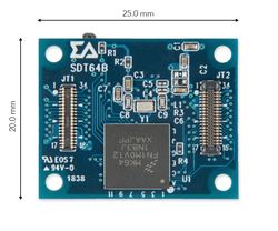
Overview
SDT64B has been designed by Sigma Delta Technologies for easy prototyping of IoT devices. The coin-sized board is equipped with ethernet and high-performance MCU enabling direct firmware update. Direct firmware update makes it ideal for smart connected devices. MK64FN1M0VDC12 MCU features ARM® Cortex® -M4F core, with 256KB RAM and 1MB flash memory. The board provides peripherals of three UART interfaces, three SPI interfaces, two I²C interfaces, seven GPIO pins, two 12-Bit ADCs and one 12-Bit DAC.
Board Features
- MCU
- Kinetis MK64FN1M0VDC12 in 121 XFBGA
- Arm® Cortex®-M4F, up to 120MHz
- Ethernet
- Microchip KSZ8081RNACA in 24 QFN
- 10BASE-T/100BASE-TX IEEE 802.3 Compliant Ethernet Transceive
- RMII interface IEEE1588 capable
- Power
- 5V(VBUS) for power supply
- 3.3V for I/O Voltage
- Memories
- 1MB Flash memory
- 256KB RAM
- Secure
- Supporting DES, 3DES, AES, MD5, SHA-1, and SHA-256 algorithms
- Serial Peripherals
- 3 x UART interface
- 3 x SPI interface
- 2 x I²C interface
- 7 x GPIO [0:6]
- 2 x 12-Bit ADC
- 1 x 12-Bit DAC
- JTAG
- Serial Wire Debug (SWD)
#Sigma Delta Technologies
DAP Station & Interface
At Sigma Delta Technologies Inc., the SDT Board is a board with a target MCU which can be connected with the DAP Station through micro-connectors (JB1, 2 of SDT Board and JT1, 2 of DAP Station). SDT Boards are used with the DAP Station and Interface for easy programming and debugging.

SDT Boards cannot be programmed independently, so please refer to the below links for DAP Station and Interface.
- DAP Station : https://www.sigma-delta.tech/dap-stations
- Interface : https://www.sigma-delta.tech/in11
Board Pinout
1. JB Pinout
The JB1 and JB2 of SDT Board should be connected to JT1 and JT2 of DAP Station

The following pins are connected to the DAP Station:
- 3 types of power connector: VBUS, VCC, 3.3V
- I/O Pin
- 2 x 12-Bit Single-ended ADC
- 1 x 12-bit DAC
- 7 x GPIO
- Communication Pin
- 3 x UART Interface
- 3 x SPI Interface
- 2 x I²C Interface
- 1 x Ethernet Interface
- JTAG
- SWD
- GND
JT Pinout
This connector enables peripherals to be attached on top of the SDT Board. There are a comparably fewer number of pins than JB1 and JB2 of the SDT Board.

The following pins are connected to the above JT1 and JT2:
- 2 types of power connector: VBUS, 3.3V
- I/O Pin
- 2 x 12-Bit Single-ended ADC
- 1 x 12-bit DAC
- 6 x GPIO
- Communication Pin
- 2 x UART Interface
- 2 x SPI Interface
- 2 x I²C Interface
- GND
Pin names
Getting Started with mbed
1. Connect your microcontroller to a PC
Use the USB lead to connect your mbed to a PC. The status light will come on, indicating it has power. After a few seconds of activity, the PC will recognize the mbed Microcontroller as a standard USB drive.
 |  |
| Windows XP example | Mac OS X example |
2. Click the MBED.HTM link to get logged in
Go to the new USB Drive, and click MBED.HTM to open it in a web browser.
If you do not have an mbed account, choose "Signup", and create your mbed Account. Otherwise, login with your normal username and password.
This will give you access to the website, tools, libraries and documentation.
PC Configuration
Your mbed Microcontroller can appear on your computer as a serial port. On Mac and Linux, this will happen by default. For Windows, you need to install a driver:
Windows
See Windows-serial-configuration for full details about setting up Windows for serial communication with your mbed Microcontroller
From a host PC to communicate with mbed you will need a terminal application. This allows the mbed Microcontroller to print to your PC screen, and for you to send characters back to your mbed.
- Terminals - Using Terminal applications to communicate between the Host PC and the mbed Micrcontroller
Some terminal programs (e.g. TeraTerm) list the available serial ports by name. However, if you do need to know the identity of the serial port so that you can attach a terminal or an application to it:
| Windows | Mac | Linux | ||||
| Find the identity of the COM port by opening ''Device Manager''. To do this navigate ''Start -> Control Panel -> System -> Hardware -> Device Manager''. | To find the device name under Mac OS X, use the command ''ls /dev/tty.usbmodem*'' | To find the device name under Linux, use the command ''ls /dev/ttyACM*'' | ||||
 |  |  |
Example Code
Import programSDT-example-blinky
Example for Serial communication and LED Blinky
Last commit 08 Oct 2018 by  SDT Inc.
https://os.mbed.com/teams/Sigma-Delta-Technologies/code/SDT-example-ethernet/
https://os.mbed.com/teams/Sigma-Delta-Technologies/code/SDT-example-wifi/
For Wi-Fi example, SDT3976C(Wi-Fi Component) is needed
SDT-example-cloud
- SDT-example-cloud is only available through the CLI(Comand Line Interface)
- Reference:
https://github.com/SigmaDeltaTechnologiesInc/SDT-example-cloud/wiki#configure-network-interface
Data Sheets
See also
SDTxArm Pelion Kit
Now, SDTxArm Pelion Kit is available here!!


SDTxArm Pelion Kit Elements
- SDT64B
- DAP Station Ver.2
- IN11
- SDT3976C
- SDT6378C
- MicroSDHC 8GB(Micro SD-Card)
You need to log in to post a discussion
To compile a program for this board using Mbed CLI, use sdt64b as the target name.
Board Partner

SDT Inc.
Introducing the new paradigm of IoT by providing products and solutions for easy and reliable inter-connectivity.
Silicon Partner
NXP
NXP is a leading semiconductor company founded by Philips more than 50 years ago.
 Mbed Enabled
- Advanced
- Baseline
Mbed OS support
- Mbed OS 2
- Mbed OS 5.10
- Mbed OS 5.11
- Mbed OS 5.12
- Mbed OS 5.13
- Mbed OS 5.14
- Mbed OS 5.15
- Mbed OS 6.0
- Mbed OS 6.1
- Mbed OS 6.10
- Mbed OS 6.11
- Mbed OS 6.12
- Mbed OS 6.13
- Mbed OS 6.14
- Mbed OS 6.15
- Mbed OS 6.2
- Mbed OS 6.3
- Mbed OS 6.4
- Mbed OS 6.5
- Mbed OS 6.6
- Mbed OS 6.7
- Mbed OS 6.8
- Mbed OS 6.9