SDT51822B
Low-power, low-cost, operating voltage selectable BLE 4.0 board for IoT
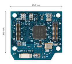
Overview
SDT51822B has been designed by Sigma Delta Technologies for easy prototyping of IoT devices. This tiny, low-cost BLE 4.0 enabled board is equipped with 0.25°C resolution temperature sensor, making it suitable for connectivity devices. The nRF51822-QFAC MCU features 32bit Arm® Cortex® - M0 core. In addition, there is operating power selection option of 1.8V for low power and 3.3V for high performance. The board provides pheripherals of one UART interface, two SPI interfaces, two I²C interfaces, three GPIO pins and four 8/9/10-Bit ADCs.
Board Features
- MCU
- Nordic nRF51822-QFAC in 48 QFN
- ARM® Cortex®-M0, 16MHz
- Bluetooth® low energy V4
- Receiver Sensitivity : -93 dBm in 1Mbps BLE mode
- Transmit Maximum power : 4dBm
- Power consumption: TX(0dBM): 8.0mA, RX(1Msps): 9.7mA
- Temperature sensor
- 0.25° C resolution.
- Power
- 1.8V, 3.3V Selectable power voltage depending on the situation
- 5V(VBUS) for power supply
- Memories
- 256KB Flash memory
- 32KB RAM
- Security
- Supporting AES-128
- Serial Peripherals
- 1 x UART interface
- 2 x SPI interface
- 2 x I²C interface
- 3 x GPIO
- 4 x 8/9/10-Bit ADC
- Serial Wire Debug (SWD)
#Sigma Delta Technologies
DAP Station & Interface
At Sigma Delta Technologies Inc., the SDT Board is a board with a target MCU which can be connected with the DAP Station through micro-connectors. SDT Boards are used with the DAP Station and Interface for easy programming and debugging.

SDT Boards can not be programmed independently, so please refer to the below links for DAP Station and Interface.
- DAP Station : https://www.sigma-delta.tech/dap-stations
- Interface : https://www.sigma-delta.tech/in11
Board Pinout
1. JB Pinout
The JB1 and JB2 of SDT Board should be connected to JT1 and JT2 of DAP Station

The following pins are connected to the DAP Station:
- 4 types of power connector: VBUS, VCC, 3.3V, 1.8V
- I/O Pin
- 4 x 8/9/10-Bit ADC
- 3 x GPIO
- Communication Pin
- 1 x UART Interface
- 2 x SPI Interface
- 2 x I²C Interface
- SWD
- GND
JT Pinout
This connector enables peripherals to be attached on top of the SDT Board. There are comparably fewer number of pins than JB1 and JB2 of the SDT Board.

The following pins are connected to the above JT1 and JT2:
- 3 types of power connector: VBUS, 3.3V, 1.8V
- I/O Pin
- 4 x 8/9/10-Bit ADC
- 3 x GPIO
- Communication Pin
- 1 x UART Interface
- 2 x SPI Interface
- 2 x I²C Interface
- GND
Pin names
Getting Started with mbed
1. Connect your microcontroller to a PC
Use the USB lead to connect your mbed to a PC. The status light will come on, indicating it has power. After a few seconds of activity, the PC will recognise the mbed Microcontroller as a standard USB drive.
 |  |
| Windows XP example | Mac OS X example |
2. Click the MBED.HTM link to get logged in
Go to the new USB Drive, and click MBED.HTM to open it in a web browser.
If you do not have an mbed account, choose "Signup", and create your mbed Account. Otherwise, log in with your normal username and password.
This will give you access to the website, tools, libraries and documentation.
PC Configuration
Your mbed Microcontroller can appear on your computer as a serial port. On Mac and Linux, this will happen by default. For Windows, you need to install a driver:
Windows
See Windows-serial-configuration for full details about setting up Windows for serial communication with your mbed Microcontroller
From a host PC to communicate with mbed you will need a terminal application. This allows the mbed Microcontroller to print to your PC screen, and for you to send characters back to your mbed.
- Terminals - Using Terminal applications to communicate between the Host PC and the mbed Micrcontroller
Some terminal programs (e.g. TeraTerm) list the available serial ports by name. However, if you do need to know the identity of the serial port so that you can attach a terminal or an application to it:
| Windows | Mac | Linux | ||||
| Find the identity of the COM port by opening ''Device Manager''. To do this navigate ''Start -> Control Panel -> System -> Hardware -> Device Manager''. | To find the device name under Mac OS X, use the command ''ls /dev/tty.usbmodem*'' | To find the device name under Linux, use the command ''ls /dev/ttyACM*'' | ||||
 |  |  |
Example Code
Import programSDT-example-blinky
Example for Serial communication and LED Blinky
Last commit 08 Oct 2018 by  SDT Inc.
Import programSDT-example-ble-uart-gps
Example for GPS with SDT BLE Board
Last commit 17 Sep 2018 by SDT Inc.
Import programSDT-example-ble-uart-echo
Example for Healthcare Kit
Last commit 12 Oct 2018 by SDT Inc.
Data Sheets
See also
You need to log in to post a discussion
To compile a program for this board using Mbed CLI, use sdt51822b as the target name.
Board Partner

SDT Inc.
Introducing the new paradigm of IoT by providing products and solutions for easy and reliable inter-connectivity.
Silicon Partner
Nordic Semiconductor
Nordic Semiconductor is a fabless semiconductor company specializing in ultra low-power wireless SoCs and connectivity devices for the 2.4 GHz ISM band.
 Mbed Enabled
- Baseline
Mbed OS support
- Mbed OS 5.10
- Mbed OS 5.11
- Mbed OS 5.12
- Mbed OS 5.13
- Mbed OS 5.14
- Mbed OS 5.15