AnalogIn problem

10 Oct 2009

I've noticed a problem with AnalogIn giving values of 1.0 (or 0xFFFF) spuriously - and other invalid values - even though the pin in question is held at a fixed DC value (e.g. 0V but I've also tried other DC levels).

If I run the middle example in AnalogIn Examples section from the Handbook - the one with "AnalogIn reading 16-bit samples" in the opening comment then I see:

....

197, 0x0000
198, 0x0000
199, 0x0000
200, 0xFFFF
201, 0x0000
202, 0x0000
....

282, 0x0000
283, 0x0000
284, 0x0000
285, 0xFFFF
286, 0x0000
287, 0x0000
288, 0x0000
289, 0x0000
....

Is this a hardware fault with my board (I've tried on p15 and p20 so far with the same spurious results)?

10 Oct 2009

Hi Rob,

Rob Dobson wrote:
I've noticed a problem with AnalogIn giving values of 1.0 (or 0xFFFF) spuriously - and other invalid values - even though the pin in question is held at a fixed DC value...
... Is this a hardware fault with my board (I've tried on p15 and p20 so far with the same spurious results)?

It doesn't sound like a board fault that would occur (at least I can't think of why/how at the moment). I'll get a test rig built next week to see if we can reproduce it. If so, we should be able to track it down. If not, we can perhaps investigate your particular hardware further.

Thanks for the report!

Simon

10 Oct 2009

Hi Simon

Thanks for the quick response!

I've been investigating further as has Nick Ager (across the other side of London).  Initially it didn't look as though he could reproduce it but now I think he has.

What I've done is to to modify the "AnalogIn reading 16-bit samples" example to only display values above 0x100 as follows:

    ...
    for(int i=0; i<1024; i++) {
        if (samples[i] > 0x100)
            printf("%d, 0x%04X\n", i, samples[i]);
    ...  

I then tried shorting p20 directly to ground as shown:

Running the program doesn't show up any values above 0x100 on the 10 or so runs I tried.

I then added a single jumper to the analog input line with the free end dangling in space! - as shown:

Amazingly running the program sometimes results in one or small number of values above 0x100:

Results:
2, 0x1DA1
104, 0xFFEF
840, 0x88D8

Then I modified it again slightly and use two jumpers with the middle of the two connected together by another part of the breadboard - I've tried this in lots of other ways with similar results:

This gives several values above 0x100 each time I run the program:

Results:
68, 0x0420
204, 0xFFDF
516, 0xFCFF
528, 0x3273
880, 0x2872
884, 0x8CF8
1012, 0x4244
Results:
236, 0xFFFF
628, 0x4784
788, 0x7FD7
Results:
164, 0x0410
284, 0x3ED3
536, 0xFFFF
584, 0x1801
928, 0x6E76
Results:
8, 0xA08A
124, 0x40C4
128, 0xFFFF
240, 0xFFFF
364, 0xAD8A
412, 0x0400
424, 0x01C0
468, 0x2062
644, 0xF35F
712, 0x0C80
784, 0x7FF7
816, 0x7EF7
856, 0xCFFC
892, 0x0800
904, 0xBFDB
948, 0xA6FA
988, 0xCEEC

Please let me know if I can provide other info.

Regards

Rob

27 Oct 2009

Hi Guys

Any progress on this?

Thanks

Rob

27 Oct 2009 . Edited: 27 Oct 2009

Hi Rob,

Yes, this is almost certainly noise. I suspect it is down to a mix of capacitive coupling (e.g. bread board tracks!), no ground planes (flying wires!) and possibly some other things. We could certainly reproduce it.

There may be some simple tricks and techniques to minimise this, but we haven't had a chance to properly investigate them (hence the delay in response, sorry). A combination of some hardware techniques (shorter wires, ground plane if you are doing a board etc) and software techniques (averaging/voting) could possibly be applied, and i'm sure their are other things?

If anyone has more experience with analog design and ADC noise, maybe they can chime in.

Simon

02 Nov 2009

Hi Simon

Thanks for the response.  I can see that noise almost certainly plays a part in this because the values read depend on the external connections to the extent that when the pin is shorted directly there are no spurious values and when longer and longer cables are used the proportion of spurious values to valid ones increases.

However. electrical noise doesn't explan why the values are so wildly varying.  So I don't feel that a susceptibility to noise is sufficient explanation in itself.  I feel there must be some software (or less likely hardware) issue too because otherwise the values would be proportional to the noise level and they clearly aren't.  The values go from no noise detected at all (when the pin is directly connected to ground) to containing a number of pretty much random values (when a second connection via the bread board is in the loop).

As regards eliminating the values in software that's a bit of an impossibility as I see it.  It is easy to use thresholding to remove values like 0xffff but it is surely impossible to use thresholding or an averaging approach to remove the kind of random spurious values that are documented in my 10 Oct post above.

Regards

Rob

21 Nov 2009

I'm seeing a similiar problem from trying out the code below;  

  while(1) {
   if (ain>0.5)
    led_a = 1;
      else led_a = 0;
    }

When the ain input connected to a 10K pot I see small random flashes from the LED when ain is less than 0.5, when obviously it should be off. I agree with the conversations above; although the mbed board has been designed with signal integrity considerations as soon as we take signals off the mbed then we introduce a whole host of integrity problems, such as reflections, capacitive loadings, ground bounce and not forgetting pickup from the rf/em coupling into long jumper wires etc.

In my case I've simply added a 0.1nF capacitor between the ain (pin 15) and ground (pin1) and the problem goes away!

Chris

21 Nov 2009

In each of the examples you pictured,i noticed as you stated the issue became worse i saw your "anntenna" or lead length became longer. cell phone,fluorescent lighting,  broadcast towers, and even transmission lines can cause it. Lets face it most people have wireless internet you dont need a long wire to pick that signal up 4.68 inches for a full wave or 2.34 for half. brilliant idea chris for the dc stop.

21 Nov 2009

hey guys, step one is to put a scope on that pin with the flying leads and see what it reports in these conditions.  You'd be surprised how noise can creep in.  I had a case of a CPU design implemented in a handful of FPGAs sitting on my desk that would spuriously reset and/or get hung up.  I put a scope on it and saw a huge burst of noise on most of the pins at random times that corresponded with the hang.  As I debugged further I realized that every time I leaned forward to look at the scope, it would trigger on the burst of noise.  It was static from the back of my shirt rubbing on the chair, and only a particular motion would produce it.

You can help the situation by creating your own twisted pairs or by cutting up a network cable and using the pairs you find in there.  The tighter the spiral the better.  Use a pair of wires for each analog signal, with one wire carrying the signal and the other connected to ground, at both ends if possible.  The long bus lines of your protoboard work well for this.  Your code will have to be tolerant of spurious values, using averaging or some other kind of filtering.  And keep in mind that you probably can't do really delicate analog stuff on a protoboard.

give that a try and let us know...

--steve

21 Nov 2009

You may want to use a low pass filter on the input aswell, a simple RC filter may help.

29 Nov 2009

I also had this problem. I was surprised to see the amount of noise that was being picked up. If you are measuring low frequency (DC like) voltages, I found a 100nF from the A/D to ground helps. If you need to read higher frequency signals you will need a lowpass filter.

It is also possible to implement an averaging filter in code (at the expense of a reduced sampling frequency and additional computation.) 

02 Jan 2010 . Edited: 02 Jan 2010

I'm seeing exactly this problem with just a 5 k pot between ground and the 3.3v line. On breadboard at least, it happens even with a 100n cap from the analog in to ground if the pot is near the ground end and it happens even if averaging 512 readings at 1mS intervals, as below (though it's worse if only a few reaadings are averaged)


float  LightControl::averageInput(int no_of_averages)
{
    int i = 0;
    float average = 0;
    for ( i = 0; i < no_of_averages; i++)            
        {
            average += input.read();
           wait(0.001);    // wait 1mS between reading inputs
        }
    return average/i;
}

(input in this case is pin 20)

This certainly appears to be a noise problem, especially as it's worse at low levels of input voltage. Judging from the information that has been published on the board (that which I've found so far, at least), it looks to me as if the analog side of the design may have been compromised somewhat, which won't help - for instance, it appears from the published schematic that VDDA and VREFP are only isolated from VDD3.3V by a 10uH inductor and VREFN/VSSA seem to be connected to the general earth which VSS is connected to, although it does say in the LPC17xx User manual, page 101, that VREFP/VDDA "...can be connected to the same
supply as VDD(3V3) but should be isolated to minimize noise and error.) and that VREFN/VSSA "...should be the same voltage as VSS but should be isolated to minimize noise and error.". Speaking as someone who has in the past designed high end audio adc's commercially, I would say that, ideally, there should be a completely separate analog ground, brought out on a separate pin and who's only connection to the mbed VSS plane should be via a high value resistor - it shouldn't even overlap ground or power supply planes if at all possible. However, that's clearly impractical to do, as it would need a change in form factor to a 42pin DIP layout but you can make some improvement by adding extra ground connections directly to the board, though that is not an exercise for the faint hearted!  One good place, as it is close to the both the LPC1768  and the mbed's analog input pins, is LED1's ground end (end nearest pin 20). I will try and get some photo's of this and upload them, when I have time.

One other comment - you won't necessarily get and accurate picture with a scope. Attaaching probes can (or rather, will ) change things. The changes you get are sometimes for the better, sometimes for the worse - and I'm speaking from bitter experience, here...

Best

Dave Malham

03 Jan 2010 . Edited: 03 Jan 2010

Just adding my two cents, I tested an IR captor and used the example #3 of AnalogIn handbook yesterday. If the IR captor was alone on the breadboard with the mbed, the example runs perfectly. When I added the NokiaLCD to display values on screen rather than on leds, I had a whole bunch of wrong data caused by noise. Thus I did something similar to what Dave just sent and averaged 25 readings. This completely removed the noise in the reading. Now I have a lots of toys on the breadboard and IR is OK.


By the way, the most "noisy" test I have done so far was the HTTPserver. I have about 10cm of unprotected wires between the mbed and the RJ45 plug. It so noisy, I cannot use my wireless mouse with this setup on the table !!!

03 Jan 2010


Stephane ROCHON wrote:

By the way, the most "noisy" test I have done so far was the HTTPserver. I have about 10cm of unprotected wires between the mbed and the RJ45 plug. It so noisy, I cannot use my wireless mouse with this setup on the table !!!

Did you use twisted pairs or straightforward wires to the rj45? With twisted pairs it should have been ok.

There actually doesn't seem to be a lot of emc protection components on the mbed board, understandable for the cost, but a few more ferrite beads (at least) on the pins would have been good. If anyone's designing a board for the mbed to go in, that's really well worth considering - a ferrite bead as close as possible to each pin plus some capacitance at the downstream side of the line concerned (next to the mbed on inputs, other end of the bead on outputs) - all to be assessed in line with the speed of the signals expected, though Farnell part no.1653395 might be a good option for most pins if you are not running at too high a speed (say over a few meg - see datasheet). Bit fiddly to hand solder, but not impossible.


Dave

03 Jan 2010

The 10cm of wires connecting the mbed to the RJ45 plug were straightforward. I did not expect that small range of untwisted could be that noisy !

03 Jan 2010

Stephane ROCHON wrote:

The 10cm of wires connecting the mbed to the RJ45 plug were straightforward. I did not expect that small range of untwisted could be that noisy !

I believe most wireless mice operate in the 2.4 gHz ISM band, where the wavelengths are off the order of 6-7 cm, so your 10cm of wire is a pretty darn good antenna!


Dave

04 Jan 2010

It would be great to hear if anyone has actually succeeded in getting AnalogIn to work without the noise problems.  Maybe someone has developed their own analog input functions and bypassed the MBED library?

Personally I feel disappointed that the issue hasn't been properly recognised by the MBED folks.  There is clearly a high sensitivity to noise but I still don't think that's the only problem.  The question of why the returned values are so widely varying when there is noise does not seem to have been considered at all.  Indeed a post about numerical averaging was put up (outside this thread) and, frankly, I don't think the author had really considered what the effect of averaging such widely ranging values would be.  Just inserting some of the numbers from the third post in this thread into one of the averaging functions would have shown the author how impossible it is to average out such vastly incorrect data values.

In my opinion there is a software problem (in addition to the noise susceptibility) - probably to do with the way the values are normalised. In any case if the libraries were open source the problem (if there is one) would be found rapidly.  Instead it has been almost 3 months since my initial post and, in my opinion, the true nature of the problem still hasn't been recognised, never mind addressed, by the MBED people.  It is a bit disappointing in my view.

For now I've moved on to other prototyping platforms but I keep checking back as I really like the MBED concept - I just wish that either (a) the problems that have been found were properly thought through and reasolved or (b) the library source was available.

04 Jan 2010

I doubt anything is wrong with the software implementation of AnalogIn. The input is likely to be very high impedance and as a result it is very succeptable to noise. As Dave mentioned earlier, a better layout could help the issue but that's up to the developers. At home, I get spikes about every second that completely saturate the input for one sample.. When I work in a lab at school, the spikes are gone. It depends on the enviroment you are working in. Signals from things like cell phones, wireless phones, wifi, wireless mice and keyboards etc.. can finld ways to creep in (especially on breadboards..)

I know this is not what you wanted to hear, but a problem such as this is always easy to fix.

You can try enclosing the mbed in a conductive enclosure maybe ? 


04 Jan 2010 . Edited: 04 Jan 2010

Hi Rob,

I too would like to get to the bottom of this; sorry to disappoint you about the time it has taken for us to officially address it.

I'd definitely encourage people to have a play directly with the analog hardware (or any functions of the chip for that matter). The high-level libraries are certainly meant to help get going, but are not meant to stand in the way of you writing directly to the hardware as you would normally.

Here is some basic code I just put together for you to control the ADC directly - please feel free to have a play around:

// analog input p20 (ADC0[5], pin 3) test

#include "mbed.h"

int main() {

    // power on, clk divider /4
    LPC_SC->PCONP |= (1 << 12);          
    LPC_SC->PCLKSEL0 &= ~(0x3 << 24);    
        
    // software-controlled ADC settings
    LPC_ADC->ADCR = (0 << 0) // SEL: 0 = no channels selected
              | (25 << 8)    // CLKDIV: PCLK max ~= 25MHz, /25 to give safe 1MHz
              | (0 << 16)    // BURST: 0 = software control 
              | (0 << 17)    // CLKS: not applicable 
              | (1 << 21)    // PDN: 1 = operational
              | (0 << 24)    // START: 0 = no start
              | (0 << 27);   // EDGE: not applicable

    // setup P1_31 as sel 3 (ADC), mode 2 (no pull)    
    LPC_PINCON->PINSEL3 &= ~((unsigned int)0x3 << 30);
    LPC_PINCON->PINSEL3 |= (unsigned int)0x3 << 30;
    
    LPC_PINCON->PINMODE3 &= ~((unsigned int)0x3 << 30);
    LPC_PINCON->PINMODE3 |= (unsigned int)0x2 << 30;

    while(1) {
        // Select channel and start conversion
        LPC_ADC->ADCR &= ~0xFF;
        LPC_ADC->ADCR |= 1 << 5; // ADC0[5]
        LPC_ADC->ADCR |= 1 << 24;
    
        // Repeatedly get the sample data until DONE bit
        unsigned int data;
        do {
           data = LPC_ADC->ADGDR;
        } while ((data & ((unsigned int)1 << 31)) == 0);

        // Stop conversion    
        LPC_ADC->ADCR &= ~(1 << 24);
    
        printf("0x%3X\n", data);   
    }
}

analogin

It'd be great to hear how you get on, and if you identify any issues.

Simon

04 Jan 2010

Hmm.. I might just have to eat my words :)

If it is possible to set the pin to pull-down, it might help the noise by intoducing a lower input impedance. Is the pull-down mode compatible with the A/D? 

04 Jan 2010

If it is in software, the only thing I can think of is that somehow it's failing to wait for the conversion to complete and that the code is simply reading the data too fast - the ADC needs 65 clocks to complete - before the conversion is complete.I can't see this happening unless the code is using software delays rather than polling the appropriate DONE bit in the A/D Status register.


What I would like to see in the AnalogIn function is the ability to set a clock source for conversions (software timing of sample rates is a poor option at best and downright bad if there are interrupts from other code fragments or any form of multi threading is going on) and to be able to pass a buffer to it so that the ADC samples at truly regular and uses the buffer to absorb varying software delays.

04 Jan 2010

Whoops - Simon's response came in whilst I was typing my response so I see you are checking the DONE bit


Dave

04 Jan 2010

Blimey, this one seems to go on and on..............

I don't know if I agree with Rob's conclusions and am confused about he's comment;

The question of why the returned values are so widely varying when there is noise does not seem to have been considered at all..

Errm... isn't it the very nature of noise that the signal varies widely? It appears to me from the examples I've done that the problem is hardware related and probably due to PCB tracking/layout conflicting with the linking wires and development breadboards. I've also found that I can eliminate the noise by either placing a decoupling cap close to the analogIn and ground or even using a simple opamp buffer arrangement (capacitor feedback).

In reality you would never design a commercial product where you would directly feed an analogue source to an ADC perpherial, without first some form of  signal conditioning and/or software averaging, purely because of noise. So I don't know why so many people seem to be surprised they found noise when they haven't applied standard analog design techniques. 

Of course ferrite beads (LC) could of been placed on each pin (and personally I would of done this as it is good practise). Perhaps if there is a second revision of the board the mbed folks could incorporate (I'm open to offers!) this.

Perhaps some people are expecting a little too much?

04 Jan 2010

Simon - thanks very much for the code snippet - I will certainly do some investigation and report back.

As regards the points about noise varying widely I maybe need to clarify my comment and thoughts.  Electrical noise (of the kind we're talking about here - not thermal noise) is a signal like any other.  Noise certainly can "vary widely" but this is when considered from a frequency domain perspective.  What I meant is that from a time domain perspective the measured level of noise would be expected to vary in some way proportionately to the "strength" of the noise source.

When I short the analog input pin to ground using a jumper wire with no additional connection to the breadboard the ADC measured no noise whatsoever.  The returned values were all 0.  When I used two jumper wires connected together using a breadboard track the measured noise didn't become one or two bits of ADC value - they jumped around all over the place.

This is akin to putting a scope probe on a pin that is connected to ground (through a reasonably short cable) and noticing not 10mV of noise (which might be expected) but over 3V of noise.  To achieve this in a piece of wire no more than 20cm long with one end connected to ground would require quite a strong source of noise!

04 Jan 2010


Rob Dobson wrote:

Simon - thanks very much for the code snippet - I will certainly do some investigation and report back.

As regards the points about noise varying widely I maybe need to clarify my comment and thoughts.  Electrical noise (of the kind we're talking about here - not thermal noise) is a signal like any other.  Noise certainly can "vary widely" but this is when considered from a frequency domain perspective.  What I meant is that from a time domain perspective the measured level of noise would be expected to vary in some way proportionately to the "strength" of the noise source.

When I short the analog input pin to ground using a jumper wire with no additional connection to the breadboard the ADC measured no noise whatsoever.  The returned values were all 0.  When I used two jumper wires connected together using a breadboard track the measured noise didn't become one or two bits of ADC value - they jumped around all over the place.

This is akin to putting a scope probe on a pin that is connected to ground (through a reasonably short cable) and noticing not 10mV of noise (which might be expected) but over 3V of noise.  To achieve this in a piece of wire no more than 20cm long with one end connected to ground would require quite a strong source of noise!

Hi Rob, I have observed exactly what you described above, volts of noise being coupled into a circuit from static electricity.  In my case it was a scope probe that did the coupling, which you would think would be pretty well shielded.  Have you tried using the twisted pairs to connect the analog in?  Or the other external filtering ideas?

--steve


04 Jan 2010 . Edited: 04 Jan 2010

Okay, some reuslts. Firstly, I have added an extra groundplane to the Mbed using some thin (0.75mm) pcb I had, cut to size (19mm wide x 52 mm long), mounted under the mbed between the mounting strip of the pins.

view of groundplane fitted to mbed 
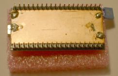
Notice the solder blobs. The midle one on the left connects the top and bottom of the pcb together - it does not connect to anywhere else - and certainly not to the shield of the USB connector, which must NOT be connected to ground at the Mbed end.

The other blobs are wires going to the topside of the Mbed - top left goes to pin 1, the two on the right go to the grounded end of two of the LED's. Note that, although it should not be possible to short out to any of the components on the underside of the Mbed, I added some insulation, just in case.

Looking at the top of the modified Mbed, you can see the connections to pin 1 and the LED's.

Top of the modified Mbed
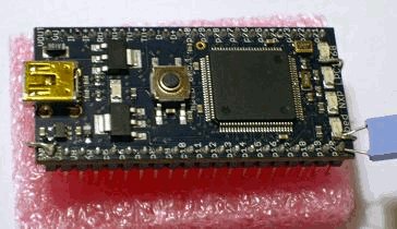
You can also see at the bottm right, a (blue) 100nF capacitor from the AdcInput on pin 20 and the ground connection on LED1 (which also connects to the new groundplane).


I modified the code that Simon posted, so that the printf statement read;


printf("0x%3X\n \r", data >>4); 

since the twelve bits of data from the ADC are in bits 15:4 of ADGDR, the bottom four bits being reserved (presumably being for devices with a 16 bit converter) and seemingly containing garbage, judging from printouts). Then, non-averaged values, with the whole thing is mounted on a breadboard with another Mbed doing something else and the ADC driven from a simple 5k pot, go like this;


0x850084B
0x8500845
0x850084B
0x850084B
0x8500851
0x850084B
0x8500849
0x850084B
0x8500845
0x850084B
0x850084B
0x850084B
0x850084B
0x850084B
0x850084B
0x8500845
0x850084B
0x850084B
0x8500848
0x850084B
0x850084B
0x850084B
0x8500845
0x850084B
0x850084B


As you can see, there's a few LSB's worth of jitter (noise) but no major excursions - clearly a bit of averaging would give good results. In fact, if the noise is sufficiently noise like (and is external to the LPC1768), this could be treated as dither, which means that an average over more, say, 32 readings, would effectively increase the resolution to 16 bits (or more). However, if you are attempting to use this, you should maybe still put some code in to discard outlier values that fall to far away from the average - anyway, just a thought....


Dave


05 Jan 2010 . Edited: 05 Jan 2010

Perhaps the next revision of the mbed can include a grould plane layer in the PCB?

By the way, I don't see this as an issue with the mbed. A/D applications almost always call for careful implementations (ground plane above being a very good example). If you really need a clean signal you shouldn't even think about working on breadboards...

I am surprised that the ground plane did such a good job. Nice work!

05 Jan 2010

I tried Simon's code and found it gave the same results for me as using AnalogIn. I then looked up the various ADC settings and found that I couldn't understand the CLKDIV and PCLK settings especially in view of this post: http://mbed.org/forum/topic/229/

Can someone point me in the direction of documentation on PCLKSEL0 and PCLKSEL1 please especially relating to the ADC clock speed.

So I tried a bit of tinkering with the values and found that if I make the value of CLKDIV 200 (<< 8) (rather than 25 << 8 in the example) the ADC runs rather more slowly - I'm not certain how slowly:

// software-controlled ADC settings
LPC_ADC->ADCR = (0 << 0) // SEL: 0 = no channels selected
| (200 << 8)    // CLKDIV: PCLK max
| (0 << 16)    // BURST: 0 = software control
| (0 << 17)    // CLKS: not applicable
| (1 << 21)    // PDN: 1 = operational
| (0 << 24)    // START: 0 = no start
| (0 << 27);   // EDGE: not applicable

When I tested it this removed the widely varying spurious values and I found that even when I used a long drum of cable as a noise antenna (in a similar arrangement to my photos at the start of this thread - with a patch wire connecting pin20 to ground) I could only get the odd 0x3ff value which would be easy to filter out.  I didn't see the widely varying spurious values I'd seen before.  I'm not sure if this is really helping towards any kind of understanding or whether it is just an interesting observation. I've also tried a potential divider from Vout to ground with a 1nF capacitor and see similar results.

05 Jan 2010

I have now added some stats calculations to the ADC capture test and published here: http://mbed.org/users/Bobty/programs/gpdz5c

My results for low noise situations (I have taken used short cables and a 1nF capacitor between p20 and ground - although the MBED is still on a breadboard and connections are made through the breadboard) with the CLKDIV values of 25 and 200 are:

CLKDIV = 25

Mean: 184.19                Std-dev (highest, lowest): 10.27, 0.68
Deviation Table
Dist.   Count
0       87184
1       13367
2       1252
3       343
4       249
5       2
6       1
7       0
8       0
9       0
> 10    2

CLKDIV = 200

Mean: 183.92        Std-dev (highest, lowest): 0.71, 0.62
Deviation Table
Dist.   Count
0       88949
1       11185
2       1791
3       393
4       78
5       4
6       0
7       0
8       0
9       0
> 10    0

I have also run in a situation where I use a noise antenna as described before (a coil of wire) with these results:

CLKDIV = 25

Mean: 184.22
Std-dev (highest, lowest): 37.05, 0.73
Deviation Table
Dist.   Count
0       76163
1       22088
2       2862
3       807
4       310
5       95
6       3
7       2
8       1
9       0
> 10    69

CLKDIV = 200

Mean: 183.85
Std-dev (highest, lowest): 26.23, 0.75
Deviation Table
Dist.   Count
0       84110
1       14860
2       2372
3       828
4       188
5       19
6       1
7       2
8       0
9       0
> 10    20

This is for 102400 samples in total for each run.

I think the results show some benefit for the lower clock speed in terms of reducing spurious values but clearly the problem isn't removed by this software-only adjustment.

However, in the final run I did notice that some of the values differing from the mean by more than 10 were not 1023 (other values included: 353, 512, 798, 1020, 439, 475 and 1019).

05 Jan 2010

Igor Martinovski wrote:

Perhaps the next revision of the mbed can include a grould plane layer in the PCB?

By the way, I don't see this as an issue with the mbed. A/D applications almost always call for careful implementations (ground plane above being a very good example). If you really need a clean signal you shouldn't even think about working on breadboards...

I am surprised that the ground plane did such a good job. Nice work!

A separate analog groundplane would require an extra layer in the pcb, so might add too much to the cost, but some ground pads wouldn't have much impact and would be much easier to connect to then the LED pads!

I certainly agree about avoiding breadboards if at all possible for mixed signal apps, but sometimes you just can't avoid it at an early stage.


Dave