PCA9675_IO_Expander
PAC9675 IO Expander
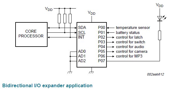
The PCA9675 is an I2C based device with 16 quasi bidirectional IO pins configurable as either input or output. The 16 pins are each capable of sinking 25mA when driving loads and is therefore useful as an LED driver. The IO pins can also be turned into input mode as well as be used to read digital inputs from switches.

It is important when driving this device to ensure that the correct IO configuration is set as a pin configured for output mode could contest with an input signal. The worst case scenario is when a digital input pin is has a logic 1 applied to it and the pin is inadvertantly driven as an output with logic 0 output. In this scenario a high level of current will flow into the device, causing possible damage.
With this suite of software a class has been created for the PCA9675. This object class allows the user to select which I2C peripheral he wants to use with the device and to also to assign a custom I2C slave address. The slave address must be the same as what is configured in hardware for the device, but the C++ class does allow for multiple objects/devices connected to the same I2C bus.
Complete Software Listing Here
NXP Device Data Sheet Here
Set up the device
To use the class the user must first include the relevant header files:
#include "mbed.h"
#include "misra_types.h"                         /* MISRA Types */
#include "PCA9675.h"
and then create an I2C object on which the PCA9675 will sit
I2C CNTRL_i2c(p9, p10);
In this case the I2C object is called CNTRL_i2c and uses pins p9 and 10 on the mbed module. Secondly the user must then create the object for the PCA9675 specifying which I2C bus he wants to use and the I2C slave address for the device
PCA9675 BaseBoardLatch(&CNTRL_i2c, PCA9675_BASE_BOARD_SLAVE_ADDRESS);
Here the object is called BaseBoardLatch, the I2C bus used in the one we have just created called CNTRL_i2c, and the slave address is referenced via a #define.
This is all you need to do to setup the device. Every thing else from here on down relates to actually using the device.
Using the functions
Once the setup is done you can read the identity information contained within the device. This is included in each part and is accessed via an I2C sequence described in detail in the datasheet. The ID information consists of the manufacturers identity, the part identity and the die revision. Each manufacturer has its own unique id (0 in the case of NXP). Reading this information initially will give you some confidence that the I2C is working correctly and you can communiate with the device. The public function looks like this:
sint32_t read_device_ID(uint8_t *manufacturer, uint16_t *part_ident, uint8_t *die_revision);
The manufacturer ID is 8 bits wide, the part_ident is 13 bits wide and the die revision information is 3 bits wide. Hence using 8, 16 and 8 bit unsigned integers respectively will be sufficient to hold the data.
The return value for the function is 0 is the device has been accessed successfully (ACK) otherwise a non zero number is returned (NACK). An enum can be used to reference the return value. It's name is eI2C_ACK.
The calling function can use the comparison with objectname.enumvalue (BaseBoardLatch.eI2C_ACK in this case) to determie if the call has been successful or not.
To configure the IO direction for the device the user must call the following function with two 8 bit byte paramters which refelct the IO direction for the individual IO pins. A logic 0 reflects an output pin and a logic 1 reflects an input pin. The function also resets the device to the power up state before applying the direction information to the latches.
sint32_t init(uint8_t port0_Direction, uint8_t port1_Direction);
Again the retrun parameter from the function is the ACK/NACK from the I2C bus, either zero (successful) or non zero (not successful). The IO direction information is stored locally within the class and is used as a mask when writing data to the IO pins. When wirting data, it is not possible to change the IO direction. To change the IO direction the init() function needs to be called again. Once the direction has been set the user can then write data to the device or read data from the device using the following two functions:
sint32_t write_data(uint8_t port0_payload, uint8_t port1_payload);
sint32_t read_data(uint8_t *read_port0, uint8_t *read_port1);
The write data takes two bytes of data and writes them to the port pins.
If the IO direction is set as input then the write is ignored. This is done on a bit by bit basis for each of the pins, using a mask from the intial direction setup function. This prevents unwanted changes in IO direction.
Reading the data using the read_data() function requires the use of two pointers to return data to the calling function.
The actual return value for both function is again the I2C ACK/NACK signal. ie the return value is ACK == 0 == BaseBoardLatch.eI2C_ACK for a successfull reception of data.
The final function is the read_slave_address();
uint8_t read_slave_address();
This function allows you to read the I2C slave address of the PCA9675 object you have created.
Software
The full software for this is available here.