PowerSwitch Tail II
 jim hamblen.
1 reply
jim hamblen.
1 reply
The PowerSwitch Tail is a low-cost module designed to switch AC loads such as household lights and appliances using a digital logic control signal. The US version is rated at 120VAC 15A. For safety and especially if you do not have prior experience working with high voltage AC, a sealed device such as the Power Switch Tail II seen below is a safer alternative to switch small household AC devices rather than building a high voltage AC circuit on a breadboard or even a small relay breakout board or SSR breakout board with a bare PCB without a case. It has an internal switch module and the high voltage connections are all enclosed in the case. Standard AC plugs are already attached. International versions of the Power Switch Tail are also available. On the international version, an extension cord (with the correct plug types for the country) can be cut in two and soldered or screwed onto the board inside the case and one of the two versions is setup for countries with higher voltages. The high voltage international version (i.e., for 200-240VAC) has a relay with a higher voltage coil and higher voltage surge suppression MOVs. The US version is also available from Sparkfun. Another handy feature is that the internal driver circuit for the relay is setup so that an external DC power supply is not needed for mbed to drive the relay, the USB power will suffice. Any digital output pin on mbed will drive it directly.

The Power Switch Tail II has an internal driver and relay circuit with the standard AC plugs for the US

Add your own AC plugs to the PowerSwitch Tail IIU international version kit and attach the cover

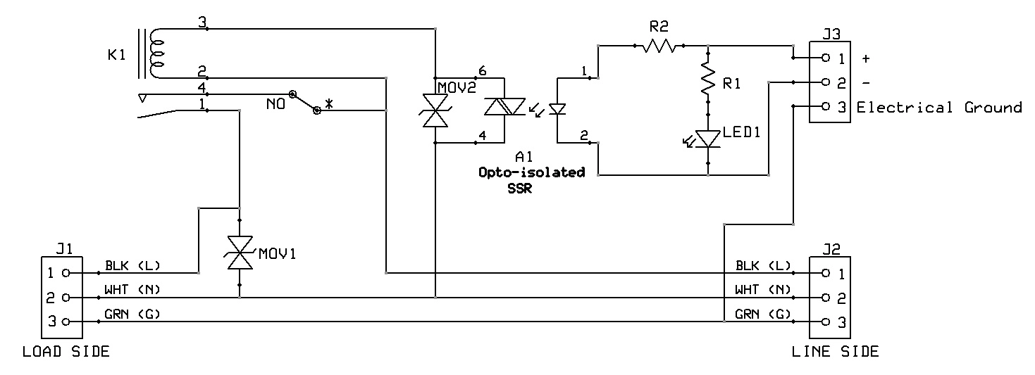
Power Switch Tail II Schematic
In the schematic above, A1 is a VO2223 0.9A 600V optically isolated TRIAC (Phototriac) in a DIP package that is used to drive the mechanical relay. Note that it also has two MOVs included for surge suppression. The module can switch up to 120VAC 15A loads, and the internal relay is rated at 240V 40A. Since a TRIAC drives the relay, it cannot be used for DC switching (TRIACs only work with AC). The image below shows the PCB inside the case. The two red wires attached to screw terminals are the digital control signal and logic ground. It will operate off of a 3.3V or 5V logic output signal and it draws about the same current as a small LED. Several Power Switch Tail modules could be used using mbed's USB cable power without the need for an external DC power supply for mbed. The digital connections can be made without opening the safety case, but here is a view of the PCB inside.

PowerSwitch Tail II with safety cover off to view PCB
Safety Note on High Voltages
Leave the cover on when using the module. A high voltage power line shorted to a digital logic circuit on a breadboard can blow up an entire computer system, or cause electrocution if touched. For safety, keep the wires for any high voltage and/or high current devices well away from the breadboard and do not touch them when power is on. Even a momentary wire short can blow things ups. An inline fuse and even a GFI breaker is not a bad idea. Long before a standard household AC circuit breaker trips, electronic parts will blow out with a short. Breadboard contacts and small jumper wires only handle about one amp. For electrical isolation, when using a relay to control external AC devices, do not connect the grounds on the power supplies from the control side to the load side.
Any digital out pin can be used to control the relay (connects to the input of the relay driver circuit).
Here is an example program the turns the relay on and off every 4 seconds.
#include "mbed.h"

DigitalOut myled(LED1);
DigitalOut Ctrl(p8);

int main() {
    while(1) {
        Ctrl = 1;
        myled = 1;
        wait(2);
        Ctrl = 0;
        myled = 0;
        wait(2);
    }
}
The digital output control signal (mbed P8) and a logic ground (mbed gnd pin 1) are connected using a small screw terminal block built into the case of the PowerSwitch Tail. The AC connections use standard AC plugs. The digital signals are optically isolated from the AC load.
Wiring
| mbed | PowerSwitch Tail | AC Device | AC wall outlet |
|---|---|---|---|
| gnd | 2 -in | ||
| P8 | 1 +in | ||
| 3 (AC) gnd | |||
| AC female plug | AC male plug | ||
| AC male plug | AC wall socket |
PowerSwitch Tail turning lamp on and off using a digital out pin
In the video above, the demo program is turning the lamp on and off every four seconds. Note the audible click of the relay and the red LED indicator on the PowerSwitch Tail. LED1 is also turning on and off on the mbed module, but it is a bit hard to see in the video.
Since this device uses a relay for switching, it cannot dim the light. In addition to the standard relay version, a Power Switch Tail with a solid state relay (SSR) is also available (up to a 300W non inductive load).The PowerSwitch SSR version can dim lights when used with the zero crossing module (syncs to AC phase). The SSR version should not be used on inductive loads. There is also a PowerState module to detect if an AC device is turned on. Drivers, Relays, and Solid State Relays describes some other options and circuits to drive high current and/or high voltage AC and DC devices.
1 comment on PowerSwitch Tail II:

Please log in to post comments.
I try to control the on off of a LED light bulb with it, in the on position the bulb light up very bright but in the off position the bulb still has an extremely dim light (not totally off). Did you try any LED light bulb?