EMC Testing mbed
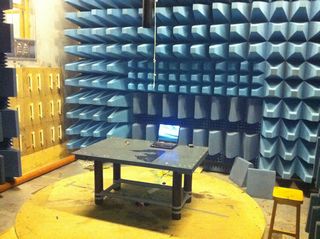
The mbed NXP LPC11U24 is now entering its final stages of testing before release. The hardware is good, the libraries are good, production test is in place, and so it is time to do some more formal testing. Last week I booked an hour in the anechoic chamber at dB Technology to see what the radiated emission characteristics of mbed NXP LPC11U24 look like.
EMC Requirements
All electronic products are required to be tested for their compliance to various regulations for electromagnetic emissions and immunity, unless they are exempt for a particular reason. As mbed is not an end product but a testing and prototyping tool/module not intended for domestic use, full compliance is not required. However, Should any one design a product that uses mbed, the final product would be required to comply, and so we had them tested just to get a benchmark of their performance.
The test house
As Cambridge, UK, has a very active electronics design community, it is not surprising to find that EMC testing facilities are not too far away. To test mbed, we used a local company dB Technology based just a few miles north of Cambridge, in a village called Cottenham, with Dave Smith being the Engineer assign to see us through the process.
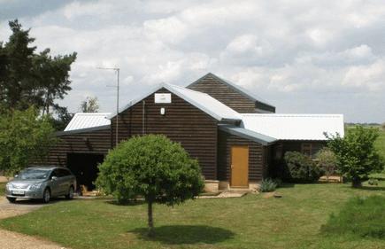 |
| dB technology, in a nice rural location! |
The tests
For our purposes, we were only doing radiated emissions testing and not carrying out any immunity testing. This required a 1 hour slot in the anechoic chamber at dB Technology.
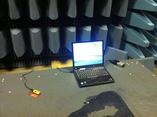 |  |
| mbed in a workshop board - ready! | mbed on rotating platform in the Chamber |
For the test the mbed would be running a "worst case" scenario, one that would lead to the highest emissions. This means using interfaces that have high frequency clocks, toggling pins and transmitting data. For the LCP1768 mbed, this is sending Ethernet packets and communicating with the host over USB, while the LPC11U24 mbed was just the USB functionality.
As the test progresses the platform rotates so the that test test up is viewed from all angles by the antenna. For the first set of tests the equipment is sweeping from 25MHz to 1GHz, looking for emissions in this part of the spectrum. The antenna is on a pneumatic mount, and halfway through the test a surprising "Psssssssht" signals that the sweep/rotate process is now taking place with the antenna polarized vertically!
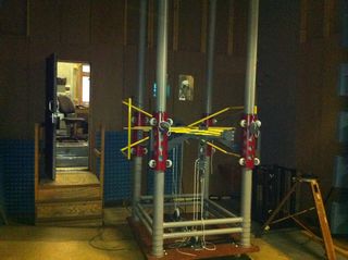 | 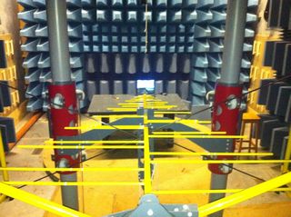 |
| The Antenna on its pneumatic mount. | Looking down the "barrel" of the Antenna at mbed. |
When the testing to 1GHz is completed, there is a brief pause while the antenna is changed to one that is suitable for 1GHz and upwards. Although our testing will only go to 3GHz, the test equipment at dB technology is capable to testing up to 26GHz!
The test equipment is a fairly unassuming stack of instrumentation and measurement equipment not really out of place in a lab environment. The really impressive part of the process is the automation. It seems that, at least for this basic testing, there is a template test result document, and that test data capture is automated, as is the formatting and insertion of the data into the test report! It is only a 15 minute drive back to the office, but my phone notified me that I'd received an email when I was less than half way, and the email had the test report attached.
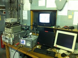 | 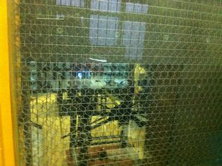 |
| Unassuming stack of test kit. | Peeking through the mesh into the chamber |
All of the test rooms are RF sheilded by having the walls, floors and ceilings completely clad in metal sheeting, needless to say, I was not available to talk on my cellphone during the test. Even the windows were made with glass containing wire mess, and then covered with several addition layers of wire mesh.
In case of emergency
One of the most curious things I saw was the emergency equipment by the exit of the control room. All the usual fayre, electrical isolation, fire extinguishers, panic button. Oh, and a solar powered calculator. Go figure - literally!
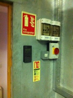 |
| In case of emergency, compute the optimal escape route? |
The results
The results are interesting and give an indication of mbeds EMC performance. They can be summarised as :
- The LPC11U24 mbed, across the full spectrum there is a healthy margin between emissions, and the allowable limit for industrial use. There are also good margins for teh domistic allowable limit, except a single spike at around 200MHz
- The LPC1768 mbed is significantly more spiky, with one violation of the more relaxed "industrial" limits at 48MHz. At other points the more strict "domestic" limits are breached.
6 comments on EMC Testing mbed:
You need to log in to post a discussion


Was the 48MHz spike (mbed NXP LPC1768 EMC Results) from the mbed or the laptop? As the laptop is directly in front of the antenna and in the 3m test range. What was the mbed PLL running at 100Mhz or 96MHz? Was there any ferrites (clamps) over the USB cable?